GOS-6200 OSCILLOSCOPE GOS-6200 OSCILLOSCOPE USER MANUAL USER MANUAL CONTENTS PAGE 1. PRODUCT INTRODUCTION................................................. 1 1-1.Description………………………………………………. 1 1-2.Feature………………………………………………….... 2 2. TECHNICAL SPECIFICATIONS………………………… 4 3. PRECAUTIONS BEFORE OPERATION…….…………... 3-1.Unpacking the instrument………………….………….... 3-2.Checking the Line Voltage…………………..………….. 3-3.Environment……………………………………..……… 3-4.Equipment Installation and Operation……………….... 3-5.
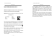
GOS-6200 OSCILLOSCOPE GOS-6200 OSCILLOSCOPE USER MANUAL FOR UNITED KINGDOM ONLY NOTE: This lead/appliance must only be wired by competent persons WARNING: THIS APPLIANCE MUST BE EARTHED IMPORTANT: The wires in this lead are coloured in accordance with the following code: Green/ Yellow: Blue: Brown: USER MANUAL This cable/appliance should be protected by a suitably rated and approved HBC mains fuse: refer to the rating information on the equipment and/or user instructions for details.
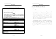
GOS-6200 OSCILLOSCOPE GOS-6200 OSCILLOSCOPE USER MANUAL EC Declaration of Conformity We GOOD WILL INSTRUMENT CO., LTD. USER MANUAL 1.PRODUCT INTRODUCTION 1-1. Description No. 7-1, Jhongsing Rd., Tucheng City, Taipei County 236, Taiwan The GOS-6200 is a 200MHz, two-channel, dual-sweep, portable oscilloscope GOOD WILL INSTRUMENT (SUZHOU) CO., LTD. No.69 Lushan Road, Suzhou New District Jiangsu, China. for general purpose use.
GOS-6200 OSCILLOSCOPE GOS-6200 OSCILLOSCOPE USER MANUAL USER MANUAL 1-2.Features Additionally, the oscilloscope offers several other features: 1) High intensity and internal graticule CRT 7) Trigger signal output The signal selected by the TRIGGER SOURCE is available. This The oscilloscope employs a high intensity 6-inch retangular type output may be used to connect to a frequency counter or other cathode-ray tube with red internal graticule. It displays clear readable instrument.
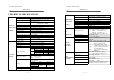
GOS-6200 OSCILLOSCOPE GOS-6200 OSCILLOSCOPE USER MANUAL USER MANUAL 2.TECHNICAL SPECIFICATIONS 2mV~5V/DIV, 11 steps in 1-2-5 sequence ±3% (5 DIV at the center display ) Continuously variable to 1/2.5 or less than Vernier Vertical Sensitivity panel-indicated value Frequency Bandwidth(-3dB) DC ~ 200MHz (5mV/DIV:DC~150MHz) (2mV/DIV:DC ~ 20MHz) Rise Time 1.75ns(5mV/DIV:2.33ns) (2mV/DIV:17.
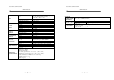
GOS-6200 OSCILLOSCOPE GOS-6200 OSCILLOSCOPE USER MANUAL Type CRT Z-AXIS INPUT TRIGGER SIGNAL OUTPUT CALIBRATOR OUTPUT SPECIAL FUNCTION LINE POWER REQUIREMENT OPERATING ENVIRONMENT Phosphor Accelerating Potential Illumination Coupling Voltage Maximum Input Voltage Bandwidth Voltage Frequency Response Output Impedance Waveform Voltage Impedance Auto Set USER MANUAL 6-inch rectangular type with internal graticule 0%, 10%, 90% and 100% markers. 8 x 10 DIV (1 DIV = 1 cm) P31 14.5kV approx.
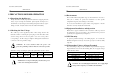
GOS-6200 OSCILLOSCOPE GOS-6200 OSCILLOSCOPE USER MANUAL USER MANUAL 3.PRECAUTIONS BEFORE OPERATION 3-3.Environment The normal ambient temperature range of this instrument is from 0° to 3-1.Unpacking the Oscilloscope The product has been fully inspected and tested before shipping from the 40°C (32° to 104°F). To operate the instrument over this specific factory. Upon receiving the instrument, please unpack and inspect it to temperature range may cause damage to the circuits.
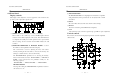
GOS-6200 OSCILLOSCOPE GOS-6200 OSCILLOSCOPE USER MANUAL USER MANUAL 4. PANEL INTRODUCTION After the instrument is switched on, all the important settings are displayed in the readout. The LED’s located on the front panel assist operation and indicate additional information. Incorrect operation and the electrical end positions of control knobs are indicated by a warning beep.
GOS-6200 OSCILLOSCOPE GOS-6200 OSCILLOSCOPE USER MANUAL 4-1.Front Panel Display controls USER MANUAL (3).TRACE ROTATION The TRACE ROTATION is for aligning the horizontal trace in parallel The display controls adjust the on-screen appearance of the waveform and with graticule lines. This potentiometer can be adjusted with a small provide a probe compensation signal source. screwdriver. (4).FOCUS The control knob effects both the trace and the readout sharply. (5).
GOS-6200 OSCILLOSCOPE GOS-6200 OSCILLOSCOPE USER MANUAL (7).20MHz BWL – Pushbutton with indicator LED. USER MANUAL (11)TRACE SEP Briefly pressing the pushbutton, the bandwidth is reduced to approx. The instrument contains a trace separate function which is required in 20MHz, and the measurement is made by eliminating undesired high the alternate time base mode to separate the DELAY time base trace(s) frequency signal from the waveform.
GOS-6200 OSCILLOSCOPE GOS-6200 OSCILLOSCOPE USER MANUAL USER MANUAL (13)CH1 VOLTS/DIV. (17)CH1 AC/DC. (14)CH2 VOLTS/DIV– Control knob for channel 1/channel 2 has double (18)CH2 AC/DC function. Pressing the pushbutton briefly to switch over from AC (~ symbol) to Turning the knob clockwise to increase the sensitivity in 1-2-5 sequence DC (= symbol) input coupling. The setting is displayed in the readout and turning it in the opposite direction (CCW) to decrease.
GOS-6200 OSCILLOSCOPE GOS-6200 OSCILLOSCOPE USER MANUAL Horizontal controls: USER MANUAL (22)MAIN/ALT/DELAY— Pushbutton for time base mode selection. The horizontal controls select the time base operation mode and adjust the The instrument contains two-time base designated MAIN and DELAY. horizontal scale, position and magnification of the signal. With the aid of the DELAY time base, signal parts displayed by the MAIN time base can be expanded in X-direction.
GOS-6200 OSCILLOSCOPE GOS-6200 OSCILLOSCOPE USER MANUAL window segment decreases when the DELAY time coefficient is set to USER MANUAL (25)X-Y-VAR – Pushbutton with double function. a lower value (higher time deflection speed). X-Y For better reading, the vertical position of the DELAY time base trace Set to X-Y mode to select three functions sequentially by pressing the position can be shifted (please note TRACE SEP (11)). button briefly.
GOS-6200 OSCILLOSCOPE GOS-6200 OSCILLOSCOPE USER MANUAL Trigger controls USER MANUAL (26)MODE – Pushbutton and indicator LEDs. The trigger controls determine the sweep start timing for both signal and Pressing the pushbutton to select the trigger mode. The actual setting is dual trace operation. indicated by a LED.
GOS-6200 OSCILLOSCOPE GOS-6200 OSCILLOSCOPE USER MANUAL (27)TRIGGER LEVEL/TV LINE SELECT—Control knobs USER MANUAL DC TRIGGER LEVEL Couple DC and all frequency components of a triggering signal to the Turning the control knob causes a different trigger input setting trigger circuitry. (voltage), and set to a suitable position for the starting of triggered DC coupling is useful for most signals, especially for providing a sweep of the waveform.
GOS-6200 OSCILLOSCOPE GOS-6200 OSCILLOSCOPE USER MANUAL (29)SOURCE—Pushbutton and associated LEDs. USER MANUAL (30)HO-DELAY—Control knob with a double function and associated Pressing the pushbutton to select the trigger signal source or the X LED. signal for an X-Y operation. The actual setting is indicated in a LED The control knob has two different functions depending on the time and by the readout (“SOURCE”, slope, coupling). base mode.
GOS-6200 OSCILLOSCOPE GOS-6200 OSCILLOSCOPE USER MANUAL USER MANUAL (31)TV-V/TV-H/TV-STD—Pushbutton for video sync signal selection. (32)SLOPE ( )/TV SYNC POLA( )—Pushbutton for In the TV trigger mode, each time when the pushbutton of TV-V/TV- the triggering slope or video polarity selection.
GOS-6200 OSCILLOSCOPE GOS-6200 OSCILLOSCOPE USER MANUAL (33)AUTOSET— USER MANUAL (34) MEMO- 9 —SAVE/RECALL Pressing briefly the AUTOSET pushbutton to set the instrument to the The instrument contains 10 non-volatile memories, which can be used last time base mode of CH1, CH2 and DUAL. by the operator to save instrument setting and to recall them. It relates At the same time, the attenuators VOLTS/DIV are automatically set at to all controls which are electronically selected.
GOS-6200 OSCILLOSCOPE GOS-6200 OSCILLOSCOPE USER MANUAL USER MANUAL △T : Time difference measurement. Input connectors △T% : Time difference percentage measurement. The input section is where the input signals are commonly connected to (5div=100% reference). the oscilloscope. 1/△T : Frequency measurement. △θ : Phase measurement. (5div=360o reference).
GOS-6200 OSCILLOSCOPE GOS-6200 OSCILLOSCOPE USER MANUAL (39)EXT—This BNC socket is the external trigger signal input. USER MANUAL (40)Line voltage selector and input fuse holder—Select power source In dual X-Y mode, signals at this input are used for the X deflection. and contain the primary power fuse Pressing the TRIG. SOURCE (29) pushbutton until the information of The fuse rating is shown in the section of 3-2 Checking the line “EXT, slope, coupling” is shown up in the readout and the TRIG.
GOS-6200 OSCILLOSCOPE GOS-6200 OSCILLOSCOPE USER MANUAL USER MANUAL 5. OPERATION METHOD This section contains basic operation information and techniques that should be considered before proceeding any measurement. As for the location and function of instrument controls, connectors, and indicators, refer to the “Instruction of Front Panel and Rear Panel” of this manual. 5-1.Readout Display The CRT readout display indicates how to set up the instrument controls.
GOS-6200 OSCILLOSCOPE GOS-6200 OSCILLOSCOPE USER MANUAL 5-2.Connecting Input Signals Grounding USER MANUAL 5-3.Adjustments and checks Trace Rotation Adjustment The most reliable signal measurements are made when the oscilloscope Normally, when the trace is in parallel with the center horizontal graticule and the unit under test are connected by a common reference (ground lead) line, there will be no need to adjust the TRACE ROTATION. If necessary, in addition to the signal lead or probe.
GOS-6200 OSCILLOSCOPE GOS-6200 OSCILLOSCOPE USER MANUAL USER MANUAL 5-4.Function Check 7. Observe the displayed waveform and compare them with the waveforms When you start to check the operation of your oscilloscope, proceed the shown in figure 5-2. If either probe needs to be adjusted, proceed the following instruction: step 8. If either probe does not need to be adjusted, proceed the 1. Install the ×10 probes onto CH1 and CH2 inputs. “Function Check”. 2.
GOS-6200 OSCILLOSCOPE GOS-6200 OSCILLOSCOPE USER MANUAL 4. Set both CH1 and CH2 COUPLING to GND. 5. Use the CH1 and CH2 POSITION controls to align both traces on the center graticule. USER MANUAL 5-5.Basic Operation Displaying CH1 or CH2 To display the signal from a signal channel, pressing briefly the CH1 or 6. Open the CH2 INV by pressing and holding the pushbutton. CH2 pushbutton to set the oscilloscope to channel 1 or channel 2. 7.
GOS-6200 OSCILLOSCOPE GOS-6200 OSCILLOSCOPE USER MANUAL USER MANUAL Displaying the sum or difference of CH1 and CH2 Comparing Frequency and phase (Single X-Y Operation) To display the algebraic sum or difference of CH1 and CH2, proceed the To compare the frequency and phase between two signals by using the following steps: X-Y mode. The X-Y waveform displays different amplitude, frequency, 1.Set the ALT/CHOP/ADD button to ADD mode. The figure 5-6 below and phase.
GOS-6200 OSCILLOSCOPE GOS-6200 OSCILLOSCOPE USER MANUAL USER MANUAL Setting up Dual X-Y Operation To use the oscilloscope in the dual X-Y mode, proceed the following steps: 2. Set the MAIN/ALT/DELAY button to ALT mode, and set the time 1. Connect the horizontal or X-axis signal to the EXT (X) input. range of the DELAY TIME/DIVE control to be magnified. 2. Connect one of the vertical or Y-axis signal to the CH1 (Y1) input. The figure 5-9 below shows the main and delayed sweeps appear 3.
GOS-6200 OSCILLOSCOPE GOS-6200 OSCILLOSCOPE USER MANUAL USER MANUAL Magnifying Waveform Events Use the ×10 MAG pushbutton to view small portions of a waveform as which is too far back from the starting point to view by using the TIME/DIV control. To use the ×10 MAG button, proceed the following steps: 1. Adjust the TIME/DIV to the fastest sweep that displays the event. 2. Rotate the HORIZONTAL POSITION control to move the event to display on the center of screen. 3.
GOS-6200 OSCILLOSCOPE GOS-6200 OSCILLOSCOPE USER MANUAL USER MANUAL TV-V/TV-H/TV-STD pushbutton to set TV-H triggering. To trigger the The polarity of the synchronization pulse is critical for the slope selection. oscilloscope at the horizontal (signal line), press the TV-V/TV-H/TV- The figure 5-13(a) and 5-13(b) shows the examples of TV polarity STD pushbutton to set TV-L triggering. The figure 5-12(a) shows vertical synchronization signals.
GOS-6200 OSCILLOSCOPE GOS-6200 OSCILLOSCOPE USER MANUAL USER MANUAL 5-6.Measurement Application The oscilloscope has a cursor measurement system for making accurate, Figure 5-14: Cursor Measurement (a).Typical △V (Voltage difference) for AC direct-readout voltage, time, frequency and phase measurements. The voltage. measurements described in this section are examples of typical When both CH1 and CH2 are turned on, the applications using this measurement system.
GOS-6200 OSCILLOSCOPE GOS-6200 OSCILLOSCOPE USER MANUAL 1. Set the VOLTS/DIV and VAR controls to provide an exact fivedivision vertical display. USER MANUAL (g).Typical △ Θ cursor function for phase measurement. 2. Use the vertical POSITION control to control the negative amplitude A phase measurement is done by first setting of the signal on the 0% reference line and the positive amplitude on a reference for the full 360o waveform the 100% reference line. period: 3.
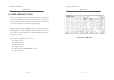
GOS-6200 OSCILLOSCOPE GOS-6200 OSCILLOSCOPE USER MANUAL USER MANUAL 6-3.Cleaning 6.MAINTENENCE To clean the oscilloscope, use a soft cloth dampened in a solution of mild The following instructions are executed by qualified personnel only. To avoid detergent and water. Do not spray cleaner directly onto the oscilloscope electrical shock, do not perform any servicing other than the operating because it may leak into the cabinet and cause damage. instructions unless you are qualified to do so.
GOS-6200 OSCILLOSCOPE USER MANUAL 7.