
Manual


APPENDIX
183
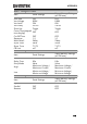
J2 Connector
Pin name
Pin number
Description
N.C.
1
N.C.
2
N.C.
3
SUM I MON
4
Connect to SUM I MON of the J1 connector.
PRL OUT+
5
Used during master/slave operation. Connected to
PRL IN+ of the J1 connector.
PRL OUT-
6
Used during master/slave operation. Connected to
PRL IN- of the J1 connector.
LOAD ON/OFF
CONT
7
N.C.
8
SLAVE RANGE
CONT
9
Used during master/slave operation. Connected to
RANGE CONT 0 of the J1 connector.
N.C.
10
N.C.
11
A COM
12
Connected to the negative load input terminal on
the rear panel.
N.C.
13
N.C.
14
N.C.
15
ALARM INPUT
16
Activates an alarm with high (or low) TTL level
signal input. Pulled up the internal circuit to 5 V.
A COM
17
Connected to the negative load input terminal.
N.C.
18
N.C.
19
+15V
20
Controls the on/off of the load booster power
(cannot be used for multiple purposes).
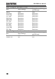
J1 Connector Booster
Pin name
Pin number
Description
N.C.
1
N.C.
2
N.C.
3