
Manual


EXTERNAL CONTROL
147
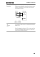
Pin out
The Range Status
pins are photo-
coupled open-
collector outputs.
17
14, 15
Photocoupler input: 30V max, 8mA, max.
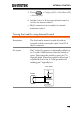
External Trigger Signal
Description
Pins 11 and 12 of the J1 connector are the
trigger signal inputs. The trigger signal is used
to resume a sequence after a pause. This action
is useful to synchronize the execution of a
sequence with another device.
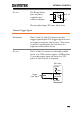
Pin out
Pin 11 of the J1 connector is internally pulled
down to A COM with an approx. 50kΩ resistor.
To use the trigger input, an active low TTL
pulse of 10μs or more is required.
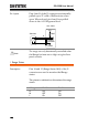
PEL-3000
Trigger
input signal
Analog
connector
12
11
A COM
A COM
50kΩ