
Manual


PEL-3000 User Manual
146
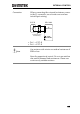
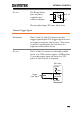
Pin Inputs
Pins 8 and 9 of the J1 connector are internally
pulled up to 5V with a 10kΩ resistor when
open. When closed, pin 8 and 9 are pulled
down to the A COM ground level.
PEL-3000
Switches
Analog
connector
12
+5V
A COM
8
9
10kΩ
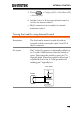
Note
The range can only be externally controlled when
the IRange has been set to High using the front
panel controls.
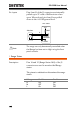
I Range Status
Description
Pins 14 and 15 (Range Status 1&2) of the J1
connector are used to monitor the IRange
status.
The pinout combination determines the range
status.
I Range
Pin 15
Pin 14
H
Off
Off
M
Off
On
L
On
Off