
Manual


EXTERNAL CONTROL
143
5. Press
Main
> Configure [F5] > Next Menu [F4]
> External [F3].
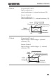
6. Set the Control to R for proportional control or
to Rinv for inverse control.
The J1 connector is now ready for external
resistance control.
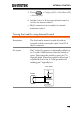
Turning the Load On using External Control
Description
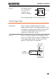
The load can be turned on and off with an
external switch connected to pins 7 and 12 of
the J1 connector.
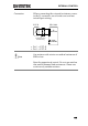
Pin Inputs
Pin 7 of the J1 connector is internally pulled up
to 5V with a 10kΩ resistor when the switch is
open. Thus when the switch is open, pin 7 is
logically high. When the switch is closed, pin 7
is pulled down to the A COM ground level,
making pin 7 logically low.
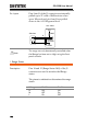
PEL-3000
Switch
Analog
connector
12
7
+5V
A COM
10kΩ