
Use and Care Manual

3
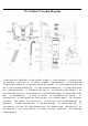
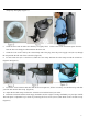
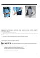
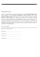
GV 10 Quart Vacuum Diagram
1. Filter guard A 2. HEPA Filter 3. Filter guard B 4. Motor 5. Thermo-protector 6. Extension Cord
(not provided) 7. Cover latch A 7a. Screws 8.switch 9.Screws(M3*25) 10. Screws(M3*15)
11.Upper part of switch box 12. Connector terminal and insulator 13. Power supply cords and cord
sets 14. Wire connector soldering log 14.1. Wire connector soldering log 15. Lower part of switch
box 16.Connection cable 17. Connection cable fixer nut 18. Connection cable fixer part 1 19.
Connection cable fixer part 2 20. Screws(M3*12) 21.Round rubber support 22. Sound muffler (Foam
filter) 23 Screws(M5*10) 24. Plastic air diffuser 25. Screw(M5*15) and washer 27.
Screws(5/16*15) 28. 10Q Canister 28.1. Grounding wire 28.2. Harness hanger 1 28.3. Aluminum
rivet 4.2*12 28.4. washer 28.5. Φ20 foot gasket 28.6. Screw (M5*10) 28.7. Fastening Nut M5 29.
Big Washer 30. Motor depression ring 31. 10Q inner dust bag 32. 10Q outer dust bag 33.
Cover seal ring 34. Cover 35.1. Bent connector tube 35.2. Screw for hose 35.3. Screw cuff 36.
Grounding wire 2 36.1. 5 wire connector 37. Handle 38. Hose 39.Harness 40. Rating label
41.Warning Label