
User's Guide


10
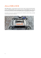
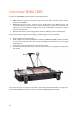
Overview MIRA HDR
In short, the MIRA HDR system comprises the following parts:
• HDR antennas; separate transmitter (Tx) and receiver (Rx) antennas with a central
frequency of 500MHz.
• MIRA antenna box; special antenna box for deployment of the MIRA system. The
‘standard’ antenna box is set-up for a regular 22-channel swath, with 12 Rx and 11 Tx
antennas, but it is possible to program any Tx-Rx combination resulting in, if all are
selected, 132 channels.
• Measurement wheel; used to trigger data collection and keep track of the distances.
To make the system complete and running, the following parts are also needed:
• Power supply for the antenna box.
• Field computer or tablet (with Windows 10x64) with MIRAsoft HDR software installed,
to collect, save and view multi-channel data. We highly recommend the use of a rugged
field computer.
• Positioning system e.g. RTK-GPS or robotic total station.
• Suitable carrier solution (to carry or pull the antenna box) or arrangement to hand-push
the system.
To connect the parts, see System set-up section. Instructions and information for carrying out a
multi-channel MIRA measurement can be found in the MIRAsoft HDR User Guide.