MALÅ MIRA HDR User Guide
Our Thanks... Thank you for choosing Guideline Geo and MALÅ as your Ground Penetrating Radar solution provider. The very core of our corporate philosophy is to provide our users with the very best products, support and services. Our development team is committed to providing you with the most technologically advanced and easy-to-use GPR products with the capability to meet your needs for efficiency and productivity now, and into the future.
Guideline Geo | MALÅ Under the copyright laws, this manual may not be copied, in whole or in part, without the written consent of Guideline Geo. Your rights to the software are governed by the accompanying software license agreement. The MALÅ logo is a trademark of Guideline Geo registered in Sweden and other countries. The product described in this document is subject to continuous developments and improvements.
Table of Contents MALÅ MIRA HDR ................................................................................................................... 1 User Guide ................................................................................................................................ 1 Our Thanks .............................................................................................................................. 2 Table of Contents ..............................................................
Preface About this Manual This manual is written for the end user of the product and explains how to set up and configure the product, as well as providing detailed instruction on its use. Additional Resources GPR Training GPR Case Studies GPR Downloads center/ www.guidelinegeo.com/support-service-advice-training/ www.guidelinegeo.com/solutions/case-stories/ www.guidelinegeo.
Safety and Compliance User Notices This GPR-device is certified according to FCC, subpart 15, IC RSS-220 and ETSI EN 302 066-1&2. You are cautioned that changes or modifications not expressly approved by the party responsible for compliance could void the user’s authority to operate the equipment. NOTE: This equipment has been tested and found to comply with the limits for a Class B digital device, pursuant to part 15 of the FCC Rules.
Radiation Exposure Statement To comply with ISED RF exposure compliance requirements, a separation distance of at least 20cm should be maintained between the EUT and all persons during normal operation Pour se conformer aux exigences de conformité d'exposition ISDE RF, une distance de séparation d'au moins 20 cm doit être maintenue entre l'EST et toutes les personnes pendant le fonctionnement normal.
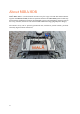
About MIRA HDR MALÅ MIRA HDR is a multi-channel antenna array for large scale 3D GPR measurements together with MIRAsoft HDR, the data acquisition software. The MIRA HDR system enables any measurement combination between the individual receiver and transmitter antennas used in the array; antennas, which are built with the MALÅ HDR technology (High Dynamic Range). The antenna array can be precisely positioned and, with dense parallel swaths, produces extremely high-resolution time slices.
Unpack. Inspect. Register Great care should be taken when unpacking the equipment. Be sure to verify the contents shown on the packing list and inspect the equipment and accessories for any loose parts or other damage. Note: The packing list that is included with the shipment should be read careful and any discrepancy should be reported to our sales department at www.guidelinegeo.com Note: All packing material should be kept in the event that any damage occurred during shipping.
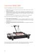
Overview MIRA HDR In short, the MIRA HDR system comprises the following parts: • • • HDR antennas; separate transmitter (Tx) and receiver (Rx) antennas with a central frequency of 500MHz. MIRA antenna box; special antenna box for deployment of the MIRA system. The ‘standard’ antenna box is set-up for a regular 22-channel swath, with 12 Rx and 11 Tx antennas, but it is possible to program any Tx-Rx combination resulting in, if all are selected, 132 channels.
System components Antennas and antenna box Antennas The MIRA HDR system is designed to handle shielded separable antennas only, no other antennas can be used with the MIRA HDR system. The MALÅ HDR antennas are designed and built to very tight tolerances to achieve a ‘near-identical’ response (signature) from each channel. The MALÅ HDR shielded antennas are available with a centre frequency of 500MHz. This frequency will cover investigations ranging from 0m to approximately 3m depth in nonconductive ground.
v v Antenna box The antenna box comes in one standard version, with 22 channels. This means 11 transmitters and 12 receivers placed in two rows within the antenna box. Tx on top and Rx on bottom. Each antenna element has its own secured slot and is connected via communication cables to the Blockmaster.
A connector panel can be found on the rear of the antenna box. Here power, GPS, Ethernet etc. are connected. Also see System set up section. The System diode blinks while the MIRA HDR system is booting; it becomes constant once the system is ready to connect to MIRAsoft HDR. The GPS diode will blink until the internal GPS clock is ready to sync with the external GPS clock (to pair the GPS coordinates with GPR traces).
provide information on coverage of your investigation area. Positioning The antenna array must be positioned with a high level of accuracy throughout the survey. A precise control of the geometry is an absolute prerequisite to make the resulting 3D radar picture correct and reliable. Centimetre accuracy is needed over the whole investigation site. The MIRA HDR system can be positioned by using an RTK GPS system and with a Total station solution (in the near future).
Some points to consider: • • • • If working in an environment with a number of trees, high buildings or other infrastructure that might disturb the communication with GPS satellites, a Total Station is preferred. In these types of environments, it can also be hard to define lines and point features with the GPS. However, on open ground with lower vegetation and/or fewer overhead obstacles, the RTK GPS solution is most often a faster and easier method of positioning.
Power Depending on your system the power supply can be customized. Preferably, a connection to the alternator of the carrying vehicle can be made but, if this is not an option, arrangements with portable power sources may be considered and solutions are provided by Guideline Geo with suitable cables and boxes. It is recommended to use a LiFe-battery for longer power supply. An ordinary car battery requires exchanges during a working day as the battery will last approximately 4-5 hours.
Note: It is important to turn off the power when the antenna array is not in use, otherwise it will drain the power supply. Accessories Carrier The prime applications for the MIRA systems are radar surveys over large areas and, practically, it may not be feasible or particularly efficient to move the array manually over thousands of square meters. To gain the maximum coverage, a motorised vehicle would be recommended.
Encoders For positioning along the measurement swaths and to control the data collection, the MIRA HDR system is compatible (together with an adapter) with all MALÅ measuring wheels.
System set up (how to connect) 1. Connect the battery cable using the provided power cable to the Power connector on the antenna box connector panel. Note: Make sure to connect the battery with correct polarity (Red = “+”, Black = “-“) otherwise a buzzer sound will be given when the cable is connected and the system will not start. 2. Connect your GPS. We provide two 12V output connectors on the system’s connector panel. Contact Guideline Geo for adapters for your brand of GPS.