3/4 HP MEAT PROCESSOR Owner’s Manual Item # 1A-MS501 READ & SAVE THESE INSTRUCTIONS
Congratulations on your Guide Gear Purchase. Take your game to the next level with field-tested Guide Gear products for a confident, competitive edge that strikes the perfect balance between performance and value. For future reference, please complete the owner’s record below: Serial Number/Lot Date Code:___________________________________ Purchase Date:________________________________________________ Save the receipt, warranty, and this manual.
Table of Contents Intended Use ......................................................................................................................................... 4 Technical Specifications ...................................................................................................................... 4 Important Safety Information .............................................................................................................. 4 Specific Operation Warnings .........................
Intended Use Process your own meats just like at the butcher shop. Save cash and get exactly what you want. Perfect for hunters, farmers, and more. The powerful 3/4 horsepower motor tackles big jobs, and the 5/8” blade can saw through frozen meat. Also included is a meat grinding attachment. This meat processor is to be used for commercial use only.
WARNING WARNING CAUTION
Specific Operation Warnings WARNING
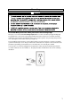
Grounding WARNING Grounded Meat processors: Meat processors with 3-Prong Plugs Meat processors marked with Grounding Required have a 3-wire cord and 3-prong grounding plug. The plug must be connected to a properly grounded outlet. If the meat processor should electrically malfunction or break down, grounding provides a low resistance path to carry electricity away from the user, reducing the risk of electric shock. (See Figure A.
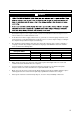
Extension Cords WARNING Grounded meat processors require a 3-wire extension cord. Double Insulated meat processors can use either a 2- or 3-wire extension cord. As the distance from the supply outlet increases, you must use a heavier gauge extension cord. Using extension cords with inadequately sized wire causes a serious drop in voltage, resulting in loss of power and possible meat processor damage. The smaller the gauge number of the wire, the greater the capacity of the cord.
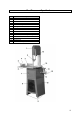
Meat Processor Specifications Part 1 2 3 4 5 6 7 8 9 10 11 12 13 14 15 Description Cover Blade Guard Fence Pusher Pusher Locking Knob Sliding Stainless Steel Table Front Access Door Front Motor Access Panel Rubber Feet Steel Stand Meat Grinder Assembly Locking Handle Tube Connector Meat Grinder Intake Stuffer Tool Blade Guard Adjustment Knob
Package Contents 1. 2. 3. 4. 5. 6. Electric Meat Cutting Band Saw with Meat Grinder 2 1/2" Grinding Plate Knife Funnel Attachment Stuffer Tool Cutting Blade Parts List Please refer to Parts List table during assembly. No. Description Qty. No. Description Specifications Qty.
Assembly WARNING To assemble the stand and motor, review the components diagram as shown in Figure 1 and the Parts List on page 10. You may choose to begin assembling the stand first and gradually add all other components. The motor housing may be attached last. Once assembled, attach the Rubber Feet to the four corners of the stand. The feet will help reduce vibration when the saw is in use.
Once the base is assembled, attach the Drive Belt to the motor wheel (A) and to the Spindle Wheel (B) in the compartment directly above. If the two wheels don’t line up properly, loosen the four bolts (C) holding the motor in place and slide the motor up or down, depending on need. Once the wheels line up, retighten the bolts. (Figure 2) Replacing and Adjusting Saw Blade WARNING steps.
Mounting a New Blade Use only authorized replacement blades (BSB-MBS) measuring 82” x 5 / 8”. To mount a new blade, begin by placing the upper portion of the blade onto the upper drive wheel, teeth facing down and toward you. While doing this, insert the blade in the slot located on the upper guide body (N). (Figure 8) Mount the lower half of the blade on the bottom drive wheel, making sure the blade goes in the slot (O) on the lower guide body.
Assembling the Power Switch WARNING The O/- power switch (O) is located in the upper corner of the Install holes. Attach the switch to the side of the steel stand using two nuts, bolts and washers (X). NOTE: Be sure O is at the top. (Figure 12) Take out the black wire and pass the black, white and green wires through cable sleeve, then insert the cable sleeve into hole site of panel (figure 13). Before the wires are connected to the terminals, please do not tighten the cable sleeve.
Assembling the Fence and Pusher The fence (CC) and pusher (DD) have predetermined spaces for attachment to the table. The fence attaches to the side, the pusher attaches to the end. Using socket screws, attach the fence and pusher to their respective areas.
Meat Grinding WARNING Attach the Meat Grinder to the machine (MM). Slide the sausage casing over the exposed Tube Connector (NN). The sausage casing is now ready to be filled with the meat of your choice. (Figure 20) As shown in Figure 20, fill the Meat Grinder Intake (OO) with meat. Using the supplied plastic Push Rod (PP), slowly press the meat into the intake. Feeding the meat into the intake will result in the meat being pumped out of the intake and into the tube connector, filling the sausage casing.
Limited Warranty The Sportsman’s Guide and Northern Tool and Equipment Company, Inc. ("We'' or ''Us'') warrants to the original purchaser only ("You" or ''Your'') that the Guide Gear product purchased will be free from material defects in both materials and workmanship, normal wear and tear excepted, for a period of one year from date of purchase. The foregoing warranty is valid only if the installation and use of the product is strictly in accordance with product instructions.