
User Manual


Expert Power Control NET 24x
2
3Expert Power Control NET 24x
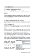
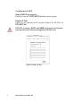
2.2 Installation
1.) Connect the power supply cable (A) with the power socket.
EPC NET 24x now is booting and shortly after ready for usage.
2.) Plug the Ethernet cable into the connector (C) on the front
side of EPC NET 24x and connect it to your Ethernet.
3.) Connect the clients to the active outlets at the EPC NET 24x
(F).
With Expert Power Control NET 24x (EPC NET 24x) electrical
devices can be switched via a TCP/IP network. There are only
two steps necessary for installation: The connection to an elec-
tric circuit and a TCP/IP network and the conguration of the IP
settings. Afterwards EPC NET 24x can be switched by all PCs
of the network.
1. Description
2.1 Extend of Delivery
Included in delivery are:
• Expert Power Control NET 24x
• CD-ROM including Software and Manual
• Short manual
2. Hardware
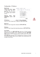
2.3 Status LED
The Status LED (B) shows different states of the device:
• Status LED red: Device is not connected to the ether-
net
• Status LED orange: Device is connected to the ether-
net, TCP/IP settings are not allocated
• Status LED green: Device is connected to the ethernet,
TCP/IP settings allocated, device is ready to use
• Status LED blinks alternately red and green: Device is
in Bootloader mode.