Expert Power Control NET 24x The 24-fold Remote Power Switch for TCP/IP networks Manual
Manual Expert Power Control NET 24x © 2008 Gude Analog- und Digitalsysteme Rev. 1.
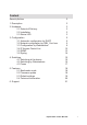
Content Security Advise 2 1. Description 3 2. Hardware 2.1 Extend of Delivery 2.2 Installation 2.3 Status LED 3 3 3 3 3. Configuration 3.1 Automatic configuration by DHCP 3.2 Network configuration by GBL_Conf.exe 3.3 Configuration by Webinterface 3.4 IP Access Control List 3.5 SNMP 3.6 Syslog 5 5 5 6 12 13 14 4. Switching 4.1 Switching at the device 4.2 Switching by Webinterface 4.3 Fuses 15 15 15 17 5. Features 5.1 Bootloader mode 5.2 Firmware update 5.3 Default settings 5.
Security Advise The device must be installed only by qualified personnel according to the following installation and operating instructions. The manufacturer does not accept responsibility in case of improper use of the device and particularly any use of equipment that may cause personal injury or material damage. The device contains no user-serviceable parts. All repairs must be performed by factorytrained service personnel. Check that the power cords, plugs and sockets are in proper condition.
1. Description With Expert Power Control NET 24x (EPC NET 24x) electrical devices can be switched via a TCP/IP network. There are only two steps necessary for installation: The connection to an electric circuit and a TCP/IP network and the configuration of the IP settings. Afterwards EPC NET 24x can be switched by all PCs of the network. 2. Hardware 2.1 Extend of Delivery Included in delivery are: • Expert Power Control NET 24x • CD-ROM including Software and Manual • Short manual 2.2 Installation 1.
A) Power Supply Cable ( 1 Plug CEE, 32 A, 1,80m (32A Version) 1 Plug CEE 3-phase, 16 A, 1,80m (3 x 16 A Version) 1 Plug CEE, 16 A, 1,80m (16A CEE Version) 1 Plug Schuko, 16A, 1,80m (16A Schuko Version) ) B) Status LED C) Ethernet connector (RJ45) D) Button „ok” E) Button „select” F) 24 Power Ports (IEC, max.
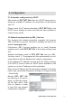
3. Configuration 3.1 Automatic configuration by DHCP After switch-on EPC NET 24x looks for a DHCP server and requests an available IP address (for deactivation of that feature see 2.2). Please check the IP adress allocated to EPC NET 24x in the DHCP server settings to make sure that the same address is used at every reboot. 3.2 Network configuration by GBL_Conf.exe For changing the network properties manually, the program GBL_Conf.exe is required. This tool is available for free on our website www.gude.
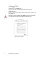
3.3 Configuration by Webinterface Go to the website of EPC NET 24x. Enter the IP address of EPC NET 24x into the address line of your internet browser: http://IP address of EPC NET 24x/ Figure 3 Login and press LOGIN. To enter the configuration menu, click on „Configuration“ on the upper left side of the screen. Configuration - Power Ports Label A name with a maximum of 15 characters can be entered here for each Power Port.
Configuration - IP Address Hostname Enter the host name of EPC NET 24x. EPC NET 24x uses this name to connect with DHCP server. Special signs may destabilize your network. IP Address Figure 5 Config - IP Address Here you can change the IP address of EPC NET 24x. Netmask Here you can change the netmask of EPC NET 24x. Gateway Here you can change the standard gateway of EPC NET 24x. Use DHCP Here you can set, if EPC NET 24x shall get its TCP/IP settings directly from your DHCP server.
Configuration IP ACL Reply ICMP-Ping requests Here you can set, if EPC NET 24x shell react on pings. Enable IP Filter Here you can activate the IP Access Control List (IP ACL) of EPC NET 24x. If IP ACL is active, DHCP and SNMP only work, if all necessary servers and clients are registered in this List.
Configuration - HTTP HTTP Port Here you can enter hte HTTP port number, if necessary. Possible numbers are 1 ... 65534 (standard: 80). To get access to EPC NET 24x, you have to enter the port number behind the IP address of EPC NET 24x: http://192.168.0.2:1720 Require HTTP Password Password protected access can be activated here. In this case, a user and an admin password have to be defined. Passwords have a maximum lengths of 15 characters.
Configuration - SNMP Enable SNMP-get Here you can activate SNMP-get protocol of EPC NET 24x. SNMP public community Here you can enter the SNMP public community. Enable SNMP-set Here you can activate SNMP-set protocol of EPC NET 24x. SNMP private community Here you can enter the SNMP private community. Download SNMP-MIB Here you can download the MIBs of EPC NET 24x.
Configuration - SNMP Trap Receiver List Enable Traps Here you can activate SNMP-traps. if enabled, EPC NET 24x will dispatch SNMP-traps to all receivers listed. Receivers have to be listed as follows: IP address (and, if necessary the HTTP port) e.g.: 192.168.0.223:8000 Trap Version Here you can choose between SNMP-traps standard 1 and 2c. Figure 9 Config - SNMP Traps Use SNMP only if your network is fitted for. More information about the SNMP functions of EPC NET 24x, you can find in chapter 3.
Configuration - Syslog Use Syslog Here you can activate Syslog of EPC NET 24x. Syslog Server IP If syslog is active enter here the IP address of you Syslog server. Figure 10 Config - Syslog Syslog Port If syslog is active enter here the port number, that your Syslog server uses to receive syslog information. More information about Syslog you can find in chapter 3.6, on http://www.gude.info/wiki or ask our support team. 3.
3.5 SNMP To get detailed status information of EPC NET 24x SNMP can be used. SNMP communicates via UDP (port 161) with EPC NET 24x: You can use SNMP to switch the power ports as well. Supported SNMP commands: - SNMPGET: request status information - SNMPGETNEXT: request the next status information - SNMPSET: EPC NET 24x request change of status You will need a Network Management System, e.g. HP-Open View, OpenNMS, Nagios etc.
SNMP-Traps SNMP-Traps are system messages, sent via SNMP-protocol to different clients. On following events, EPC NET 24x will dispatch a SNMP-Trap: - Switching of the Power Ports - Changes of the fuses You can find more information about configuration of SNMP in Chapter 3.3 or have a look at http://www.gude.info/wiki. 3.6 Syslog Syslog messages are simple text messages transmitted to a syslog server using UDP. Linux OS regularly have a syslog daemon installed, e.g. syslog-ng.
4. Switching 4.1 Switching at the device EPC NET 24x disposes of two buttons: “select” and “ok”. By pushing “select”, the LED of Power Port 1 starts blinking which means that it is selected. By pushing the button again, the next Power Port is selected. If you want to change the switching state of the selected Power Port, push the “ok” button for two seconds. Figure 11 Buttons You can check the status of the Power Ports by the color of the Power Port status LED (green=enabled/red=disabled). 4.
You can check the status of the Power Ports by the color of the Power Port status LED (green=enabled/red=disabled). Bank A / B / C Here you are able to switch the ports directly. Each Bank shows 8 Power Ports (which are secured by one fuse per 8 Power Ports (Fuse 1-3). Optionally the device can be accessed by using the the command line (e.g. for automatic or time-triggered switching). For more information please refer to our website: www.gude.
4.3 Fuses You can see the status of the fuses by the colour of the fuse LEDs Fuse 1, Fuse 2, Fuse 3). Green = enabled Red = disabled While using the webinterface you can see the states of the fuses, too. It is listed in the Control Panel. Figure 15 Fuses If one, or more than one of the fuses is shown as disabled, check the fuses, the connections and the connected devices. Each fuse secures 8 Power Ports for a power of 16A.
5. Features 5.1 Bootloader mode To activate the bootloader mode of EPC NET 24x the buttons “select” and “ok” at the front must be pushed for three seconds. In bootloader mode it is possible to disable the password protection, to update the firmware and to restore the default settings by running the program GBL_Conf.exe. The bootloader mode of EPC NET 24x is indicated by “BOOTLDR” appended to the device name in the program window of GBL_Conf.exe and by the alternately red and green blinking status led.
5.3 Default settings In order to restore the default settings EPC NET 24x must be started in bootloader mode (see 5.1). Besides that the program GBL_Conf.exe is required. Run GBL_Conf.exe and select the EPC NET 24x whose settings should be restored. Then click on Program DevicegReset to Fab default. Please notice that all current settings will be deleted. The default settings will be loaded when EPC NET 24x is restarted the next time.
5.4 Technical Information 32 A Version: Dimensions: Weight: Interface: Connections: 155 cm x 6 cm x 6 cm (LxBxT) 6 kg Ethernet RJ45 1 x Power supply cable (CEE plug, max. 32A), 24 (8x3) Power Ports (IEC-60320-C13, max. 10A) Load: 32A Load (per Port): 10A Voltage: 230V Ethernet: 10/100 Mbit 10baseT Ethernet Protocols: HTTP 1.
Connections: 1 x Power supply cable (CEE plug, max. 16A), 24 (8x3) Power Ports (IEC-60320-C13, max. 10A) Load: 32A Load (per Port): 10A Voltage: 230V Ethernet: 10/100 Mbit 10baseT Ethernet Protocols: HTTP 1.1, DHCP, SNMPv1, SNMPv2c, SNMP-Traps (v1 und v2c), Syslog Operating Temperature: 0ºC - 50ºC OS: Independent from OS (Ethernet) 16 A Schuko Version: Dimensions: Weight: Interface: Connections: 155 cm x 6 cm x 6 cm (LxBxT) 6 kg Ethernet RJ45 1 x Power supply cable (Schuko plug, max.
Konformitätserklärung / Declaration of Conformity Die Firma / The manufacturer Gude Analog- und Digitalsysteme GmbH --------------------------------------------------------------------------------------------------------------------------------------------------------------------------------------------------------------------------------------------------- Anschrift/Address: Eintrachtstr. 113, 50668 Köln Telefon/Phone: 0221 – 912 90 97 Web: www.gude.info Fax: 0221 – 912 90 98 Mail: mail@gude.
Contact Gude Analog- und Digitalsysteme GmbH Eintrachtstrasse 113 50668 Koeln Tel.:+49-221-912 90 97 Fax:+49-221-912 90 98 E-Mail: mail@Gude.info Web: www.Gude.