Type 508 ISSUE 1 Downloaded from: http://www.guardianalarms.
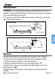
Introduction Congratulations on choosing a Dennard Series 508 Camera Housing. This operation manual provides information on the mounting variations, and access to the Series 508 Camera Housings. This operation manual will provide all the necessary information to install the Series 508 Camera Housing. Unpacking Rotate 180° Locking nut Fig.1 Locking nut Fig.2 Method The type 508 housing comes packed in the orientation shown in (fig.
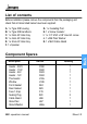
List of contents Before installation please remove the components from the packaging and check that all items listed below have been supplied. A. 1 x Type 508 housing B. 1 x Type 508 Handbook C. 1 x 3mm A/F Allen Key D. 1 x 4mm A/F Allen Key E. 1 x 5mm A/F Allen Key F. 1 x Spanner G. 1 x Insulating Pad H. 1 x Screw Insulator I. 1 x 1/4” UNC x 3/8” Hex Hd. screw J. 1 x M6 Plain Washer K.
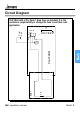
Circuit Diagram TB1 FS1 508 operation manual PTC PCB1 PLATFORM Chassis Earth FTB Cover Earth L E N Spare Unit fitted with a 20 x 5mm 1 Amp fuse as standard. It is the customers responsibility to change the fuse to suit their own application. Sheet.
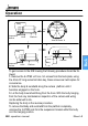
Operation 1. Body Camera Platform locates in the middle slots only Arrow ‘A’ Suspension Bracket Platform Hook View on Arrow ‘A’ 2. 3. Body Hook Suspension Bracket Hook Platform Platform Body To gain access to the 508 housing the following procedure should be followed. 1. Remove the 6 off M5 x 20 soc. hd. screws from the back plate, using the 4mm A/F long series ball allen key, these screws are held captive for convenience. 2.
Mounting Instructions 1.(2 x M6 x40 Soc. Cap hd screws) 180° 4 x M6 x 16 Soc. Hd. Screws Ceiling mounted configuration Arrow ‘A’ 2 x M6 Grub Screws View on arrow ‘A’ Housing body & sunsheild M20 Cable Gland Wall mounted configuration 3. Remove 4 x M6 x 16 Soc. Hd. screws from rear bracket and rotate cast base until desired position of M20 cable gland is acheived. Replace M6 screws and tighten firmly. to convert the housing from wall mounted to ceiling mounted orientation.
Outline Dimensions 508 Housing Outline Hidden Cable Bracket (Wall Mounted Orientation) (-90° tilt down) (+/-90° Pan) 4 off mounting holes Ø7.5 equi-spaced on a 101.6 Fused Mains Terminal Block and 6 way terminal block 84 Max 222 146 91 175 A Hidden Cable Bracket (Ceiling Mounted Orientation) (-90° tilt down) (+/-90° Pan) Locking Nuts Customer Cable Run Polycarbonate Window 10mm Thick +/-90° Pan 508 Camera Platform Outline 551 One 3 Way Fused T.B. One 6 Way T.B. 1 Slot Ø8.0 SERIAL NO.
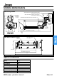
Customer Electrical Connections Housing Wiring Layout 6. 7. 9. 8. Arrow ‘B’ 5. 1. 10. 4. 2. 3. Components 1. 2. 3. 4. 5. 6. 7. 8. 9. 10. 508 operation manual Platform Gasket Housing Back Plate 423 Bracket Assembly Cable Run Locking Nut Rubber Diaphragm Sheet.
Customer Electrical Connections From Heater L E N 1 to 6 View on Rear T.B.’s Arrow ‘B’ Ref. Function L E N 1 2 3 4 5 6 Line Earth Neutral Spare Spare Spare Spare Spare Spare 508 operation manual Sheet.