Installation and Owner’s Manual Air-cooled, Prepackaged Automatic Standby Generators Models: 04389-2 (6 kW NG, 7 kW LP) 04456-2 (12 kW NG, 12 kW LP) 04390-2 (13 kW NG, 15 kW LP) GENERAC R POWER SYSTEMS, INC. R ! Not intended for use as Primary Power in place of utility or in life-support applications. DANGER DEADLY EXHAUST FUMES.
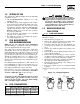
INTRODUCTION Thank you for purchasing this model of the Guardian product line by Generac Power Systems Inc. This model is a compact, high performance, air-cooled, engine-driven generator designed to automatically supply electrical power to operate critical loads during a utility power failure. This unit is factory installed in an all-weather, metal enclosure that is intended exclusively for outdoor installation.
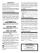
Table of Contents Guardian Air-cooled 7 kW, 12 kW and 15 kW Generators Introduction ........................Inside Front Cover Read This Manual Thoroughly ........................IFC Contents ..........................................................IFC Operation and Maintenance ............................IFC How to Obtain Service ....................................IFC Authorized Dealer Locator Number ....................IFC Safety Rules ........................................................
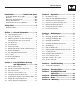
IMPORTANT SAFETY INSTRUCTIONS Guardian Air-cooled 7 kW, 12 kW and 15 kW Generators SAVE THESE INSTRUCTIONS – The manufacturer suggests that these rules for safe operation be copied and posted near the unit’s installation site. Safety should be stressed to all operators and potential operators of this equipment. ! ! WARNING: ! GENERAL HAZARDS ! ! The engine exhaust from this product contains chemicals known to the state of California to cause cancer, birth defects or other reproductive harm.
IMPORTANT SAFETY INSTRUCTIONS Guardian Air-cooled 7 kW, 12 kW and 15 kW Generators ELECTRICAL HAZARDS • All generators covered by this manual produce dangerous electrical voltages and can cause fatal electrical shock. Utility power delivers extremely high and dangerous voltages to the transfer switch as does the standby generator when it is in operation. Avoid contact with bare wires, terminals, connections, etc., while the unit is running.
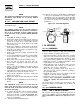
Section 1 — General Information Guardian Air-cooled 7 kW, 12 kW and 15 kW Generators DANGER ! 1.1 Only qualified electricians or contractors should attempt such installations, which must comply strictly with applicable codes, standards and regulations. UNPACKING/INSPECTION After unpacking, carefully inspect the contents for damage. • This standby generator set has been factory supplied with a weather protective enclosure that is intended for outdoor installation only.
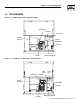
Section 1 — General Information Guardian Air-cooled 7 kW, 12 kW and 15 kW Generators 1.4 THE GENERATOR Figure 1.1 – 7 kW, Single Cylinder GH-410 Engine Oil Check/Fill Data Decal Control Panel Exhaust Enclosure Air Filter Fuel Regulator Fuel Inlet Oil Filter Battery Compartment Figure 1.2 – 12 kW and 15 kW, V-twin GT-990 Engine Oil Dipstick Data Decal Air Filter Exhaust Enclosure Control Panel Fuel Regulator Fuel Inlet Oil Filter Battery Compartment Generac® Power Systems, Inc.
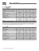
Section 1 — General Information Guardian Air-cooled 7 kW, 12 kW and 15 kW Generators 1.5 SPECIFICATIONS 1.5.1 GENERATOR Rated Max. Continuous Power Capacity (Watts*) Rated Voltage Rated Max.
Section 1 — General Information Guardian Air-cooled 7 kW, 12 kW and 15 kW Generators 1.6 SYSTEM SET LED DANGER The “System Set” LED is lit when all of the following conditions are true: 1. The AUTO/OFF/MANUAL switch is set to the AUTO position. 2. The utility voltage being supplied to the unit is being sensed by the PCB. If the utility sense voltage is not connected to the unit or if it is below 168 volts AC, then the system set light will flash rapidly.
Section 1 — General Information Guardian Air-cooled 7 kW, 12 kW and 15 kW Generators NOTE: The natural gas adjustment screw is preset during installation and should not need any further adjustment. ◆ 1.9.2 12KW AND 15KW, 990CC ENGINES 14. It may be necessary to make minor adjustments to the preset adjustment screw settings to achieve maximum power. If experiencing problems with the unit producing maximum power, follow the procedure in Section 2.6 (Adjusting the Fuel Regulator). Figure 1.
Section 1 — General Information Guardian Air-cooled 7 kW, 12 kW and 15 kW Generators • Install the transfer switch indoors on a firm, sturdy supporting structure. • To prevent switch distortion, level the switch if necessary. This can be done by placing washers between the switch enclosure and mounting surface. • Never install the switch where water or any corrosive substance might drip onto the enclosure.
Section 2 — Post Installation Start-up and Adjustments Guardian Air-cooled 7 kW, 12 kW and 15 kW Generators ! Do not open or mutilate the battery. Released electrolyte has been known to be harmful to the skin and eyes, and to be toxic. ! The electrolyte is a dilute sulfuric acid that is harmful to the skin and eyes. It is electrically conductive and corrosive.
Section 2 — Post Installation Start-up and Adjustments Guardian Air-cooled 7 kW, 12 kW and 15 kW Generators 7. When certain that utility supply voltage is compatible with transfer switch and load circuit ratings, turn OFF the utility power supply to the transfer switch. 8. On the generator panel, set the AUTO/OFF/ MANUAL switch to MANUAL. The engine should crank and start. 9. Let the engine warm up for about five minutes to allow internal temperatures to stabilize.
Section 2 — Post Installation Start-up and Adjustments Guardian Air-cooled 7 kW, 12 kW and 15 kW Generators 5. Turn ON the utility power supply to the transfer switch, using the means provided (such as a utility main line circuit breaker). 6. Set the AUTO/OFF/MANUAL switch to AUTO. The system is now ready for automatic operation. 7. Turn OFF the utility power supply to the transfer switch.
Section 2 — Post Installation Start-up and Adjustments Guardian Air-cooled 7 kW, 12 kW and 15 kW Generators If this procedure or the equipment are not available, locate the nearest Generac Guardian Dealer and they can perform the adjustments. Figure 2.4 — Full Load Speed Adjust Screw Full Load Speed Adjust Screw NOTE: A service fee may be charged for this adjustment. 2.
Section 3 — Operation Guardian Air-cooled 7 kW, 12 kW and 15 kW Generators NOTE: 3.2 USING THE AUTO/OFF/MANUAL SWITCH (FIGURE 3.1) The access panel on top of the control panel must be removed to adjust the voltage regulator. NOTE: 3.2.1 “AUTO” POSITION The voltage regulator is housed above the generator's control panel. The regulator maintains a voltage in direct proportion to frequency at a 2-to-1 ratio. For example, at 62 Hertz, line-to-neutral voltage will be 124 volts.
Section 3 — Operation Guardian Air-cooled 7 kW, 12 kW and 15 kW Generators 3. Set the generator’s AUTO/OFF/MANUAL switch to AUTO. 4. Set the generator’s main circuit breaker to its ON (or closed) position. With the preceding steps complete, the generator will start automatically when utility source voltage drops below a preset level. After the unit starts, loads are transferred to the standby power source. Refer to Section 3.4, “Sequence of Automatic Operation.” 3.
Section 3 — Operation Guardian Air-cooled 7 kW, 12 kW and 15 kW Generators 3.5.2 TRANSFER BACK TO UTILITY POWER SOURCE When utility power has been restored, transfer back to that source and shut down the generator. This can be accomplished as follows: 1. Set the generator’s main circuit breaker to its OFF (or open) position. 2. Let the engine run for a minute or two at no-load to stabilize the internal temperatures. 3. Set the generator’s AUTO/OFF/MANUAL switch to its OFF (or open) position.
Section 4 — Maintenance Guardian Air-cooled 7 kW, 12 kW and 15 kW Generators NOTE: If the fault is not repaired, the overcrank feature will continue to activate. 3.7.3.1 Approximate Crank Cycle Times • • • • • 15 seconds ON 7 seconds OFF 7 seconds ON 7 seconds OFF Repeat for 45 seconds Approximately 90 seconds total 3.7.4 OVERSPEED This feature protects the generator from damage by shutting it down if it happens to run faster than the preset limit.
Section 4 — Maintenance Guardian Air-cooled 7 kW, 12 kW and 15 kW Generators 4.3 CHANGING THE ENGINE OIL 4.3.1 ENGINE OIL RECOMMENDATIONS Use oil of American Petroleum Institute (API) Service Class SG, SH or SJ. Use all season SAE 5W-30 Synthetic oil. Organic break-in oil is required before using synthetic oil. NOTE: The unit is supplied with “break-in” oil. See the “Break-in Procedure,” Section 3.1, for the first required oil change.
Section 4 — Maintenance Guardian Air-cooled 7 kW, 12 kW and 15 kW Generators Figure 4.7 — 12 kW and 15 kW Engine Air Cleaner Screw Cover 4.7 BATTERY MAINTENANCE The battery should be inspected per the “Service Schedule,” Section 4.13. The following procedure should be followed for inspection: 1. Inspect the battery posts and cables for tightness and corrosion. Tighten and clean as necessary. 2. Check the battery fluid level of unsealed batteries and, if necessary, fill with Distilled Water Only.
Section 4 — Maintenance Guardian Air-cooled 7 kW, 12 kW and 15 kW Generators Lead-acid batteries present a risk of fire because they generate hydrogen gas. The following procedures are to be followed: • DO NOT SMOKE when near the battery; • DO NOT cause flame or spark in battery area; and • Discharge static electricity from body before touching the battery by first touching a grounded metal surface.
Section 4 — Maintenance Guardian Air-cooled 7 kW, 12 kW and 15 kW Generators The exhaust from this product gets extremely hot and remains hot after shutdown. High grass, weeds, brush, leaves, etc. must remain clear of the exhaust. Such materials may ignite and burn from the heat of the exhaust system. ! The maximum ambient temperature for the generator is 40° C (104° F). 4.10 ATTENTION AFTER SUBMERSION If the generator has been submerged in water, it MUST NOT be started and operated.
Section 4 — Maintenance Guardian Air-cooled 7 kW, 12 kW and 15 kW Generators 4.13 SERVICE SCHEDULE ATTENTION: It is recommended that all service work be performed by the nearest Generac/Guardian Authorized Dealer. SYSTEM/COMPONENT X = Action R = Replace as Necessary * = Notify Dealer if Repair is Needed.
Section 5 — Troubleshooting Guardian Air-cooled 7 kW, 12 kW and 15 kW Generators 5.1 TROUBLESHOOTING GUIDE PROBLEM CAUSE The engine will not crank. 1. Fuse blown. 2. 3. 4. 5. The engine cranks but will not start. The engine starts hard and runs rough. The Auto/Off/Manual switch is set to OFF, but the engine continues to run. There is no AC output from the generator. CORRECTION 1. Replace 15A fuse in generator control panel. Loose, corroded or defective 2.
Section 6 — Electrical Data Guardian Air-cooled 7 kW, 12 kW and 15 kW Generators Wiring Diagram – 12 & 15 kW – Drawing No.
Section 6 — Electrical Data Guardian Air-cooled 7 kW, 12 kW and 15 kW Generators Wiring Diagram – 12 & 15 kW – Drawing No.
Section 6 — Electrical Data Guardian Air-cooled 7 kW, 12 kW and 15 kW Generators Electrical Schematic – 12 & 15 kW – Drawing No.
Section 6 — Electrical Data Guardian Air-cooled 7 kW, 12 kW and 15 kW Generators Electrical Schematic – 12 & 15 kW – Drawing No.
Section 6 — Electrical Data Guardian Air-cooled 7 kW, 12 kW and 15 kW Generators Wiring Diagram – 7 kW – Drawing No.
Section 6 — Electrical Data Guardian Air-cooled 7 kW, 12 kW and 15 kW Generators Wiring Diagram – 7 kW – Drawing No.
Section 6 — Electrical Data Guardian Air-cooled 7 kW, 12 kW and 15 kW Generators Electrical Schematic – 7 kW – Drawing No.
Section 6 — Electrical Data Guardian Air-cooled 7 kW, 12 kW and 15 kW Generators Electrical Schematic – 7 kW – Drawing No.
Section 7 — Exploded Views and Parts Lists Guardian Air-cooled 7 kW, 12 kW and 15 kW Generators Enclosure – Drawing No.
Section 7 — Exploded Views and Parts Lists Guardian Air-cooled 7 kW, 12 kW and 15 kW Generators Enclosure – Drawing No. 0D3416-R ITEM PART NO. QTY.
Section 7 — Exploded Views and Parts Lists 13 29 27 38 37 22 46 10 47 45 44 48 15 35 6 38 7 21 2 4 17 49 16 23 27 8,32 8,9 34 Generac® Power Systems, Inc. 5 15 14 17 12 33 40 20 49 14 23 16 43 13 44 45 42 21 1 41 15 35 3 11 14 47 45 24 45 31 47 Guardian Air-cooled 7 kW, 12 kW and 15 kW Generators Control Panel – Drawing No.
Section 7 — Exploded Views and Parts Lists Guardian Air-cooled 7 kW, 12 kW and 15 kW Generators Control Panel – Drawing No. 0E7974 ITEM PART NO. QTY.
Section 7 — Exploded Views and Parts Lists 34 22 3B 22 16 2 17 18 36 Generac® Power Systems, Inc. 12 24 26 10 1 14 19 25 13 8 4 34 15 35 20 27 36 9 31 7 9 3A 16 21 23 32 6 11 5 3 2 33 Guardian Air-cooled 7 kW, 12 kW and 15 kW Generators 7 kW GTS Load Center Assembly – Drawing No.
Section 7 — Exploded Views and Parts Lists Guardian Air-cooled 7 kW, 12 kW and 15 kW Generators 7 kW GTS Load Center Assembly – Drawing No. 0E7975 ITEM 1 2 3 3A 3B 3C 3D 4 5 6 7 8 9 10 11 12 13 14 15 16 17 18 19 20 21 22 23 24 25 26 27 28 29 30 31 32 33 34 35 36 PART NO. QTY.
Section 7 — Exploded Views and Parts Lists Guardian Air-cooled 7 kW, 12 kW and 15 kW Generators 12 kW and 15 kW GTS Load Center Assembly – Drawing No. 0E7973-A 12 31 37 7 9 17 6 11 5 2 18 3A 9 30 36 24 10 22 16 2 27 15 13 1 3 19 25 3B 26 20 22 16 21 23 14 38 8 33 32 38 34 34 38 Generac® Power Systems, Inc.
Section 7 — Exploded Views and Parts Lists Guardian Air-cooled 7 kW, 12 kW and 15 kW Generators 12 kW and 15 kW GTS Load Center Assembly – Drawing No. 0E7973-A ITEM 1 2 3 3A 3B 3C 3D 4 5 6 7 8 9 10 11 12 13 14 15 16 17 18 19 20 21 22 23 24 25 26 27 28 29 30 31 32 33 34 35 36 37 38 39 PART NO. QTY.
40 Generac® Power Systems, Inc. 42 41 40 38 45 44 39 3 37 46 43 29 28 32 51 26 50 47 48 49 27 3 140 52 24 33 35 36 53 30 25 54 56 23 34 34 58 57 59 16A 16A 60 18 17 16B 2 22 61 15 63 19 64 20 14 13 65 73 3, 32, 33, 34, 35, 36, 40, 72 66 2, 5, 19, 20, 39, 40, 47, 64, 93, 140 12 11 1 10 2 7 9 6 3 5 4 Section 7 — Exploded Views and Parts Lists Guardian Air-cooled 7 kW, 12 kW and 15 kW Generators GT-990 Engine – Drawing No.
Section 7 — Exploded Views and Parts Lists Guardian Air-cooled 7 kW, 12 kW and 15 kW Generators GT-990 Engine – Drawing No. 0D8674-G Part 1 ITEM PART NO. QTY.
Section 7 — Exploded Views and Parts Lists Guardian Air-cooled 7 kW, 12 kW and 15 kW Generators GT-990/760 Engine – Drawing No. 0D8674-G Part 2 74 138 75 122 124 76 139 125 135 136 123 77 137 120 125 79 24 133 78 132 134 119 80 11 116 127 121 81 118 97 98 130 82 128 29 126 99 96 95 83 102 84 87 86 85 88 89 94 103 109 105 104 141 99 112 90 110 106 101 89 91 92 107 112 1 112 113 111 42 Generac® Power Systems, Inc.
Section 7 — Exploded Views and Parts Lists Guardian Air-cooled 7 kW, 12 kW and 15 kW Generators GT-990/760 Engine – Drawing No. 0D8674-G Part 2 ITEM PART NO. QTY.
Section 7 — Exploded Views and Parts Lists 14 32 31 28 11 23 5 33 31 53 7 21 51 52 39 12 13 4 6 8 9 31 37 17 38 40 34 46 45 30 3 20 47 2 22 15 36 1 1 10 17 10 30 19 5 34 32 24 16 26 35 44 34 48 28 27 28 18 28 31 32 Guardian Air-cooled 7 kW, 12 kW and 15 kW Generators 7 kW Generator – Drawing No. 0D3504-C 44 Generac® Power Systems, Inc.
Section 7 — Exploded Views and Parts Lists Guardian Air-cooled 7 kW, 12 kW and 15 kW Generators 7 kW Generator – Drawing No. 0D3504-C ITEM PART NO. QTY.
Section 7 — Exploded Views and Parts Lists 28 27 28 17 13 11 2 5 24 43 7 21 34 12 33 39 6 8 31 37 32 31 28 40 38 3 20 14 2 22 15 19 10 17 32 10 19 32 30 25 24 16 26 29 35 18 36 29 10 41 31 32 42 41 Guardian Air-cooled 7 kW, 12 kW and 15 kW Generators 12 kW and 15 kW Generator – Drawing No. 0D3417-E 46 Generac® Power Systems, Inc.
Section 7 — Exploded Views and Parts Lists Guardian Air-cooled 7 kW, 12 kW and 15 kW Generators 12 kW and 15 kW Generator – Drawing No. 0D3417-E ITEM 1 2 3 4 5 6 7 8 9 10 11 12 13 14 15 16 17 18 19 20 21 22 23 24 25 26 27 28 29 30 31 32 33 34 35 36 37 38 39 40 41 42 43 PART NO. QTY.
Section 7 — Exploded Views and Parts Lists 42 17 31 25 30 29 28 27 37 24 35 36 23 33 45 43 39 19 18 20 34 46 44 11 32 22 48 47 26 41 38 40 51 25 12 13 14 50 49 1 6 54 16 52 1 2 5 10 4 3 7 11 8 9 Guardian Air-cooled 7 kW, 12 kW and 15 kW Generators GN410 Engine – Drawing No. 0D3539-F Part 1 48 Generac® Power Systems, Inc.
Section 7 — Exploded Views and Parts Lists Guardian Air-cooled 7 kW, 12 kW and 15 kW Generators GN410 Engine – Drawing No. 0D3539-F Part 1 ITEM 1 2 3 4 5 6 7 8 9 10 11 12 13 14 15 16 17 18 19 20 21 22 23 24 25 26 27 28 29 30 31 32 33 34 35 36 37 38 39 40 41 42 43 44 45 46 47 48 49 50 51 52 53 54 PART NO.
Section 7 — Exploded Views and Parts Lists 35 34 1 14 2 5 38 6 28 6 12 7 19 6 20 41 43 45 21 40 3 39 50 Generac® Power Systems, Inc. 16 17 18 13 8 29 44 31 30 10 9 11 27 18 18 34 33 2 36 37 4 6 Guardian Air-cooled 7 kW, 12 kW and 15 kW Generators GN410 Engine – Drawing No.
Section 7 — Exploded Views and Parts Lists Guardian Air-cooled 7 kW, 12 kW and 15 kW Generators GN410 Engine – Drawing No. 0D3539-F Part 2 ITEM 1 2 3 4 5 6 7 8 9 10 11 12 13 14 15 16 17 18 19 20 21 22 23 24 25 26 27 28 29 30 31 32 33 34 35 36 37 38 39 40 41 42 43 44 45 PART NO.
Section 7 — Exploded Views and Parts Lists Guardian Air-cooled 7 kW, 12 kW and 15 kW Generators Gas Regulator – Drawing No. 0D8720-B 10 8 7 34 33 2 6 36 21 5 10 20 37 32 4 37 3 25 24 23 10 1 22 35 FOR GT 760 ENGINE ONLY 19 16 26 29 18 15 14 12 11 28 17 19 13 27 31 32 12 23 22 26 15 14 11 25 29 18 20 16 17 28 24 13 9 21 ITEM 1 2 3 4 5 6 7 8 9 10 11 12 13 14 15 16 17 18 19 20 PART NO. QTY.
716 [28 743 [29 M6PEM M6P M6PEM-T PE T LEFT SIDE VIEW 622 [24.5"] 604 [23.5"] 76.2mm [3.00"] PEA GRAVEL MINUMUM 704 [27.7"] 207 [8.14"] TRANSFER SWITCH (IF SUPPLIED) 308 [12"] FRONT VIEW 1232 [48.5"] 1193 [47"] "DO NOT LIFT BY THE ROOF" LIFTING HOLES 4-CORNERS Ø30.2mm [Ø1.19"] 149 [5.9"] RIGHT SIDE VIEW 490.7 [ AIR 260 [10.2"] **ALL DIMENSIONS IN: MILLIMETERS [INCHES] REAR VIEW ROUNDING LUG CABLE ACCESS HOLES.
Section 9 — Notes Guardian Air-cooled 7 kW, 12 kW and 15 kW Generators 54 Generac® Power Systems, Inc.
Section 9 — Notes Guardian Air-cooled 7 kW, 12 kW and 15 kW Generators Generac® Power Systems, Inc.
Section 10 – Warranty Guardian Air-cooled 7 kW, 12 kW and 15 kW Generators NOTE: This Emission Control Warranty Statement pertains to this product only IF the generator size is 15 kW or below. CALIFORNIA EMISSION CONTROL WARRANTY STATEMENT YOUR WARRANTY RIGHTS AND OBLIGATIONS The California Air Resources Board (CARB) and Generac Power Systems, Inc. (Generac) are pleased to explain the Emission Control System Warranty on your new engine.
Section 10 – Warranty Guardian Air-cooled 7 kW, 12 kW and 15 kW Generators EMISSION CONTROL SYSTEM WARRANTY Emission Control System Warranty (ECS Warranty) for 1995 and later model year engines: (a) Applicability: This warranty shall apply to 1995 and later model year engines. The ECS Warranty Period shall begin on the date the new engine or equipment is purchased by/delivered to its original, end-use purchaser/owner and shall continue for 24 consecutive months thereafter.
Section 10 – Warranty Guardian Air-cooled 7 kW, 12 kW and 15 kW Generators GENERAC POWER SYSTEMS STANDARD "TWO YEAR" LIMITED WARRANTY FOR GUARDIAN “EMERGENCY AUTOMATIC STANDBY GENERATORS” For a period of two years from the date of original sale, Generac Power Systems, Inc.