Owner’s Manual and Installation Instructions Air-cooled Recreational Vehicle Generators • Model: 02010-2 PRIMEPACT 50 • Model: 04164-3 PRIMEPACT 50LP
INTRODUCTION Thank you for purchasing this model manufactured by Generac Power Systems Inc. This model is designed and manufactured to supply electrical power for recreational vehicles. READ THIS MANUAL THOROUGHLY If any portion of this manual is not understood, contact the nearest Authorized Service Dealer for starting, operating and servicing procedures.
Table of Contents Recreational Vehicle Generator Part I – Owner’s Manual Part II – Installation Instructions Introduction ........................................ Inside Front Cover Safety Rules ...................................................................... 18 Read This Manual Thoroughly ................................. IFC Section 1 – General Information ................................. 20 Contents .................................................................. IFC 1.
Safety Rules Recreational Vehicle Generator SAVE THESE INSTRUCTIONS – The manufacturer suggests that these rules for safe operation be copied and posted in potential hazard areas of the recreational vehicle. Safety should be stressed to all operators and potential operators of this equipment. • WARNING: • The engine exhaust from this product contains chemicals known to the state of California to cause cancer, birth defects or other reproductive harm.
Safety Rules Recreational Vehicle Generator • Adequate, unobstructed flow of cooling and ventilating air is critical to correct generator operation and is required to expel toxic fumes and fuel vapors from the generator compartment. Without sufficient cooling airflow, the engine/generator quickly overheats, which causes serious damage to the generator. Do not alter the installation or permit even partial blockage of ventilation provisions, as this can seriously affect safe operation of the generator.
Section 1 – General Information Recreational Vehicle Generator 1.1 GENERATOR IDENTIFICATION Please record the following information from the generator DATA DECAL or information decal. 1. Model Number _____________________ 2. Serial Number __________________ 3. kW Rating _________________________ 4. Rated Voltage __________________ Model: 02010-2 1. 2. 3. 4.
Section 1 – General Information Recreational Vehicle Generator 1.2 GENERATOR APPLICABILITY These generators have been designed and manufactured for supplying electrical power for recreational vehicles. Do not modify the generator or use it for any application other than for what it was designed. If there are any questions pertaining to its application, write or call the factory. Do not use the unit until advised by a competent authority.
Section 1 – General Information Recreational Vehicle Generator 1.5.5 ENGINE The manufacturer does not recommend using any gasoline containing alcohol (such as “gasohol”). If using any gasoline containing alcohol, it must not contain more than 10 percent ethanol, and it must be removed from the generator during storage. Do NOT use any gasoline containing methanol. If using gasoline with alcohol, inspect more frequently for fuel leaks and other abnormalities. 1.5.
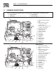
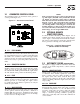
Section 2 – Operation Recreational Vehicle Generator 2.1 GENERATOR CONTROL PANEL The following features are mounted on the generator control panel (Figure 2.1): Figure 2.1 – Generator Control Panel NOTE: If the generator has been reconnected for dual voltage AC output (120/240 volts), install line breakers having an amperage rating that is different than that stated in the "Generator AC Connection System" section.
Section 2 – Operation Recreational Vehicle Generator 2.4 BEFORE STARTING THE ENGINE NOTE: Instructions and information in this manual assume the generator has been properly installed, connected, serviced, tested and adjusted by a qualified installation technician or installation contractor. 2.4.1 INSTALLATION Generator installation must have been properly completed so it complies with all applicable codes, standards and regulations and with the manufacturer's recommendations.
Section 2 – Operation Recreational Vehicle Generator NOTE: If starting from the generator control panel, turn OFF loads by setting the generator’s main circuit breaker to the OFF (or OPEN) position. If starting from a remote panel, turn OFF loads using the means provided in the vehicle (such as a main circuit breaker). Electrical load circuits will be turned ON after the generator has started, stabilized and warmed up. 2.
Section 2 – Operation Recreational Vehicle Generator 2.8.1 DO NOT OVERLOAD THE GENERATOR Read the rated wattage/amperage capacity of the generator on the generator data decal (see "Generator Identification"). Figure 2.4 – Low Oil Pressure and High Temperature Switches Applying electrical loads in excess of the unit’s rated capacity will cause the engine/generator to automatically shut down. To avoid overloading, add up the wattage of all connected electrical lighting, appliance, tool and motor loads.
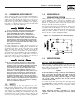
Section 3 – Maintenance Recreational Vehicle Generator 2.9.4 OVERVOLTAGE PROTECTION 2.10.3 EFFECTS OF MOISTURE AND DIRT A solid-state voltage regulator (Figure 2.6) controls the generator’s AC output voltage. This regulator supplies an excitation current to the rotor. By regulating the rotor’s excitation current, the strength of its magnetic field is regulated and, in turn, the voltage delivered to connected electrical loads is controlled.
Section 3 – Maintenance Recreational Vehicle Generator 3.2 CHANGING THE ENGINE OIL AND/OR OIL FILTER • Change the engine oil after the first 25 hours of operation. Thereafter, change the oil every 100 operating hours. Change the oil more frequently if operating consistently under heavy load or at high ambient temperatures. • Change the engine oil filter after the first 25 hours of operation, and every 100 operating hours thereafter. • To change the oil and/or oil filter, proceed as follows (see Figure 3.
Section 3 – Maintenance Recreational Vehicle Generator 5. Wrap the foam precleaner in a clean cloth and gently squeeze it dry. 6. Saturate the foam precleaner in clean engine oil. Gently squeeze it in a clean cloth to remove excess oil and to distribute oil (DO NOT TWIST). 7. Install the foam precleaner into the cover, followed by the paper filter. 8. Install the cover, foam precleaner and paper filter. 9. Tighten the two screws to retain the filter in place. Figure 3.2 – Engine Air Cleaner 3.
Section 3 – Maintenance Recreational Vehicle Generator 3.6 FUEL FILTER (GASOLINE ONLY) Remove and replace the fuel filter (Figure 3.5) once each year or every 100 hours of operation, whichever comes first. Figure 3.5 – Fuel Filter Fuel Filter 3.7 SPARK ARRESTOR MUFFLER If the generator is not equipped with a spark arrestor exhaust muffler and is to be used on any forest covered, brush covered or grass covered unimproved land, a spark arrestor may need to be installed.
Section 3 – Maintenance Recreational Vehicle Generator DANGER not dispose of the battery in a fire. The bat Do tery is capable of exploding. Storage batteries give off explosive hydrogen gas. This gas can form an explosive mixture around the battery for several hours after charging. The slightest spark can ignite the gas and cause an explosion. Such an explosion can shatter the battery and cause blindness or other injury. Any area that houses a storage battery must be properly ventilated.
Section 3 – Maintenance Recreational Vehicle Generator 3.13.2 RETURN TO SERVICE To return the unit to service after storage, proceed as follows: 1. Check the tag on the engine for oil viscosity and classification. Verify that the correct recommended oil is used in the engine (see the "Engine Oil Requirements" section). If necessary, drain and refill with the proper oil. 2. Check the state of the battery. Fill all cells of unsealed batteries to the proper level with distilled water.
PART II – INSTALLATION INSTRUCTIONS DANGER ONLY QUALIFIED ELECTRICIANS OR CONTRACTORS SHOULD ATTEMPT INSTALLATION!
Safety Rules Recreational Vehicle Generator For fire safety, installation of a generator into a recreational vehicle must comply DANGER: strictly with article 551, NFPA 70; ANSI C1-1975; AND, ANSI A119.2-1975/NFPA 501C “Standard for Recreational Vehicles” (Part 3, “Installation of Electrical Systems”). In addition, installation must comply with the manufacturer’s instructions and recommendations.
Safety Rules Recreational Vehicle Generator ELECTRICAL HAZARDS FIRE HAZARDS • The generator covered by this manual produces dangerous electrical voltages and can cause fatal electrical shock. Avoid contact with bare wires, terminals, connections, etc., while the unit is running. Ensure all appropriate covers, guards and barriers are in place before operating the generator. If work must be done around an operating unit, stand on an insulated, dry surface to reduce shock hazard.
Section 1 – General Information Recreational Vehicle Generator 1.1 PURPOSE AND SCOPE OF THE MANUAL These Installation Instructions have been prepared especially for the purpose of familiarizing installers and owners of the applicable equipment with the product's installation requirements. Give serious consideration to all information and instructions in the manual, both for safety and for continued reliable operation of the equipment.
426.7 [16.8"] SIDE EXHAUST OUTLET * ALL DIMENSIONS ARE IN MILLIMETERS [INCHES] OIL FILL " + " BATTERY CONNECTION 480.0 [18.9"] OIL DRAIN HOSE OIL FILTER AIR CLEANER 642.0 [25.3"] FUEL LINE CONNECTION OIL DIPSTICK CIRCUIT BREAKERS FUSE Section 1 – General Information Recreational Vehicle Generator Figure 1.
Section 2 – Installation Recreational Vehicle Generator 2.1 LOCATION AND SUPPORT 2.1.1 GENERATOR LOCATION The most desirable location for the generator set is between the vehicle's main frame members. However, this is seldom possible. Most units must be installed on the side of the vehicle and are difficult to reinforce. Many recreational vehicles have been factory equipped with an area for the generator set. Some vehicles may even have a generator compartment provided by the vehicle manufacturer.
Section 2 – Installation Recreational Vehicle Generator 2.1.4 GENERATOR RESTRAINT 2.2.2 COMPARTMENT CONSTRUCTION Use four 3/8"-16 hardened steel bolts (Grade 5) to fasten the generator to the supporting frame or the support tubing. These bolts must pass through (a) the generator mounting base, (b) the compartment floor (if a compartment is used) and (c) the supporting framework (Figure 2.3).
Section 2 – Installation Recreational Vehicle Generator • If flexible metal conduit is used, it must be sealed internally at the end where it terminates inside the compartment’s electrical junction box. NOTE: Flexible metal conduit, due to its unique construction, is NOT vapor tight along its entire length. • Seams and joints of the galvanized steel (whether used as a liner or for the compartment itself) must be lapped and mechanically secured.
Section 2 – Installation Recreational Vehicle Generator Figure 2.7 – Typical Noise Abatement 2.2.5 COMPARTMENT FLOOR CUTOUTS Provide openings in the generator compartment for the following items (Figure 2.8): • Engine exhaust and cooling air outlets • Generator cooling air inlet • Four holes for passage of generator mounting bolts. See the "Generator Restraint" section. DANGER lines and exhaust piping must not penetrate Fuel into the vehicle living area. Figure 2.
Section 2 – Installation Recreational Vehicle Generator 2.3 COOLING AND VENTILATING AIR It is absolutely essential that an adequate flow of air for cooling, ventilating and engine combustion be supplied to the generator set. Without sufficient airflow, the engine/generator quickly overheats. Such overheating can cause serious operating difficulties and also may cause fire and personal injury.
Section 2 – Installation Recreational Vehicle Generator Figure 2.12 – Air Inlet Using Ductwork 2.3.4 TESTING THE INSTALLATION The manufacturer recommends testing the installation to be sure adequate cooling airflow is available to the unit before placing the unit into service. If the unit shows signs of overheating, enlarge the air openings. Never place a unit into service until absolutely certain that cooling and ventilation is adequate.
Section 2 – Installation Recreational Vehicle Generator 2.4.1 FUEL TANK 2.4.2.2 Flexible Fuel Line Either the generator must share the vehicle engine's fuel tank, or a separate fuel tank must be installed for the generator set. All fuel tanks installed on the vehicle must be constructed, installed and restrained so they comply with applicable codes, standards and regulations. Use an approved flexible length of fuel hose between the generator fuel inlet connection and rigid fuel lines.
Section 2 – Installation Recreational Vehicle Generator Figure 2.15 – Typical Propane Gas Fuel System 2.5.4 PRIMARY REGULATOR Gas pressure delivered to the solenoid valve must be properly regulated by means of a primary gas regulator. Mount the primary regulator at the gas tank outlet or in the supply line from the gas tank. The following rules apply: • For best results, the primary regulator supplies gaseous fuel to the secondary regulator at 11 inches water column.
Section 2 – Installation Recreational Vehicle Generator The greater the airflow through the carburetor venturi, the lower the pressure at the venturi throat. The lower the pressure at the venturi throat, the greater the diaphragm movement, and the greater the movement of the regulator valve. The more the regulator valve opens, the greater the gas flow that is proportional to airflow through the generator.
Section 2 – Installation Recreational Vehicle Generator 2.6.1 MUFFLERS AND SPARK ARRESTORS This muffler meets code and standard requirements of the U.S. Forest Service. Use only mufflers and parts approved by the manufacturer. Any person(s) installing an unapproved muffler, or an unapproved exhaust system part, or modifying an exhaust system in any way that might cause a hazard, is liable for any damage, injury or warranty expense that might be caused by such unapproved installation or modification.
Section 2 – Installation Recreational Vehicle Generator 2.7.2 WIRING • Wiring should be of stranded copper to reduce the chance that vibration may cause breakage. • Wire gauge size should be large enough to handle at least 115 percent of the installed generator's rated maximum current. • If neutral conductors are used, they must be the same size as other leg wires.
Section 2 – Installation Recreational Vehicle Generator 2.7.6 2.7.7 POWER SUPPLY CORD The power supply cord must comply with all applicable codes, standards and regulations. It must be large enough to handle the full amperage to which it will be subjected. GROUND FAULT CIRCUIT INTERRUPTERS The National Electrical Code (NFPA 70, 551-7) requires that ground fault circuit interrupters (GFCIs) on all external and some internal electrical receptacles be installed.
Section 2 – Installation Recreational Vehicle Generator 2.8 BATTERY INSTALLATION Figure 2.20 – Connecting Battery Cables 2.8.1 RECOMMENDED BATTERY SIDE VIEW OF GENERATOR Install a battery that meets the following requirements: • The battery must be a 12-volt, automotive type storage battery. • For prevailing ambient temperatures above 32° F (0° C), use a battery rated 70 amp-hours and capable of delivering 400 cold-cranking amperes.
Section 3 – Post-installation Start-up Adjustments Recreational Vehicle Generator 2.9.1 REMOTE PANEL MODELS 3.3 The remote panels mount a rocker type start/stop switch, a “Generator Run” advisory lamp and an hourmeter. The hourmeter should be used in conjunction with the maintenance operations found in Part I of this manual.
Section 3 – Post-installation Start-up Adjustments Recreational Vehicle Generator 3.5 INSTALLATION CHECKLIST EXHAUST SYSTEM LOCATION AND SUPPORT ❑ Exhaust system complies with all applicable codes. ❑ Generator is properly located. ❑ Exhaust system is properly and safely installed. ❑ Generator is properly supported. ❑ Generator is properly restrained. ELECTRICAL CONNECTIONS GENERATOR COMPARTMENT ❑ Connections comply with local code requirements and all National Electrical Codes.
Section 4 – Troubleshooting Recreational Vehicle Generator TROUBLESHOOTING GUIDE Problem Cause Correction The engine will not crank. 1. Fuse blown 2. Loose, corroded or defective battery cables 3. Defective engine Start/Stop switch 4. Defective starter contactor 5. Defective starter motor 6. Low or defective battery 1. Replace fuse. 2. Tighten, clean or replace as necessary. 3. Replace Start/Stop switch. The engine cranks but will not start. 1. Out of fuel 2. Defective fuel pump 3.
Section 5 — Electrical Data Recreational Vehicle Generator Electrical Schematic and Wiring Diagram – Drawing No.
Section 5 — Electrical Data Recreational Vehicle Generator Electrical Schematic and Wiring Diagram – Drawing No.
Section 6 — Exploded Views and Parts Lists Recreational Vehicle Generator Regulator (Model 02010-2) – Drawing No.
Section 6 — Exploded Views and Parts Lists Recreational Vehicle Generator Regulator (Model 02010-2) – Drawing No. 0F1125-C ITEM 1 2 5 6 7 8 9 10 11 12 13 14 15 16 17 18 19 20 21 22 23 24 25 26 27 28 29 30 PART NO. 0D5694 0F4795 0F5022 0C6070 0C4680 0C4647 0C4643 0D3973 0E6183 072683A 0D3308 070728 0C5764A 0C4643A 0C6066 0C5968 0C5759 0C5761 0C6069 0C6731 0C6067 0C4706 0C6068 0C5762 045764 0C6606 0E4170 0C5760 QTY.
Section 6 — Exploded Views and Parts Lists Recreational Vehicle Generator Base and Pulleys (Model 04164-3) – Drawing No.
Section 6 — Exploded Views and Parts Lists Recreational Vehicle Generator Base and Pulleys (Model 04164-3) – Drawing No. 0F1124-C ITEM PART NO. QTY.
Section 6 — Exploded Views and Parts Lists Recreational Vehicle Generator Alternator and Panel (Model 04164-3) – Drawing No.
Section 6 — Exploded Views and Parts Lists Recreational Vehicle Generator Alternator and Panel (Model 04164-3) – Drawing No. 0D1776-F ITEM PART NO. QTY. DESCRIPTION ITEM PART NO. QTY.
Section 6 — Exploded Views and Parts Lists Recreational Vehicle Generator Engine Sheet Metal (Model 02010-2 and 04164-3) – Drawing No.
Section 6 — Exploded Views and Parts Lists Recreational Vehicle Generator Engine Sheet Metal (Model 02010-2 and 04164-3) – Drawing No. 0D1760-H ITEM PART NO. QTY.
Section 6 — Exploded Views and Parts Lists Recreational Vehicle Generator GN-410 Engine (Model 02010-2 and 04164-3) – Drawing No.
Section 6 — Exploded Views and Parts Lists Recreational Vehicle Generator GN-410 Engine (Model 02010-2 and 04164-3) – Drawing No. 0E9615-A PART NO. QTY. DESCRIPTION ITEM PART NO. QTY.
Section 6 — Exploded Views and Parts Lists 41 31 16 18 20 15 14 13 38 39 50 9 35 36 33 34 2 41 34 3 1 34 32 17 8 5 12 6 7 9 24 41 22 23 25 40 27 10 42 21 37 2 19 30 25 28 29 11 Recreational Vehicle Generator Engine Accessories (Model 04164-3) – Drawing No.
Section 6 — Exploded Views and Parts Lists Recreational Vehicle Generator Engine Accessories (Model 04164-3) – Drawing No. 0F1135 ITEM 1 2 3 4 5 6 7 8 9 10 11 12 13 14 15 16 17 18 19 20 21 22 23 24 25 26 27 28 29 30 31 32 33 34 35 36 37 38 39 40 41 42 PART NO.
Section 7 – Warranty Recreational Vehicle Generator CALIFORNIA AND FEDERAL EMISSION CONTROL WARRANTY STATEMENT YOUR WARRANTY RIGHTS AND OBLIGATIONS The California Air Resources Board (CARB) and the United States Environmental Protection Agency (EPA), together with Generac Power Systems, Inc. (Generac), are pleased to explain the Emission Control System Warranty on your new engine.
Section 7 – Warranty Recreational Vehicle Generator EMISSION CONTROL SYSTEM WARRANTY Emission Control System Warranty (ECS Warranty) for 1997 and later model year engines: (a) Applicability: This warranty shall apply to 1997 and later model year engines. The ECS Warranty Period shall begin on the date the new engine or equipment is purchased by/delivered to its original, end-use purchaser/owner and shall continue for 24 consecutive months thereafter.
Section 7 – Warranty Recreational Vehicle Generator GENERAC POWER SYSTEMS’ THREE-YEAR LIMITED WARRANTY FOR GUARDIAN RECREATIONAL VEHICLE GENERATORS NOTE: ALL UNITS MUST BE INSTALLED BY GENERAC POWER SYSTEMS AUTHORIZED SERVICE FACILITIES. For a period of 3 (three) years of operation from the date of original sale, Generac Power Systems, Inc.