Downloaded from: http://www.guardianalarms.
DVST Installation Guide January 1996 DFT-0150 INSTALLATION GUIDE Dedicated Micros UK Ltd. 11, Oak Street, Swinton, Pendlebury. Manchester. M27 4FL. United Kingdom. Direct Telephone: 0161 727 3241 Direct Fax: 0161 794 4464 Outside UK. Telephone: Int +(44) 161 727 3241 Fax: Int +(44) 161 794 4464 Dedicated Micros U.S.A. Inc. 11515 Sunset Hills Road, Reston, Virginia 22090, U.S.A. Telephone: Int +(703) 904 7738 Fax: Int +(703) 904 7743 Dedicated Micros (Australia) PTY.
6 April 1995 DVST Installation Guide Microcom ® is a registered trademark of: Microcom Systems, Inc. Gandalf ® is a registered trade mark of: Gandalf Digital Communications Ltd.
DVST Installation Guide Safety Safety Read Instructions - All the safety and operating instructions should be read before the unit is operated. Retain instructions - The safety and operating instructions should be retained for future reference. Heed warnings - All warnings on the unit and in the operating instructions should be adhered to. Follow instructions - All operating and user instructions should be followed. Cleaning - Unplug the unit from the outlet before cleaning.
Safety DVST Installation Guide Servicing - Do not attempt to service this unit yourself as opening or removing covers may expose you to dangerous voltage of other hazards. Refer all servicing to qualified service personnel. Damage Requiring Service - Unplug the unit from the outlet and refer servicing to qualified service personnel under the following conditions: (a)When the power-supply cord or plug is damaged. (b)If liquid has been spilled, or objects have fallen into the unit.
DVST Installation Guide Regulatory Notes Regulatory Notes FCC AND DOC INFORMATION (U.S.A. and Canadian Models Only) WARNING This equipment has been tested and found to comply with the limits for a Class A digital device, pursuant to part 15 of the FCC rules. These limits are designed to provide reasonable protection against harmful intereference when the equipment is operated in a commercial enviroment.
Regulatory Notes DVST Installation Guide • IEC 801-4 1988 - “Electromagnetic compatibility for industrial-process measurement and control equipment Part 4: Electrical fast transient/burst requirements”. A “ Declaration of Conformity ” in accordance with the above standards has been made and is recorded at: Dedicated Micros Ltd., Pendlebury, Manchester, England.
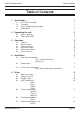
DVST Installation Guide Table of Contents Table of Contents 1 Introduction 1.1 1.2 1.3 1.4 2 Unpacking the unit 2.1 2.2 3 Callback Alarms feature Freeze all alarms No frozen images Offline frozen alarm Track last alarm Installation 4.1 4.2 4.3 5 Items in packing Packing the DVST Operation 3.1 3.2 3.3 3.4 3.5 3.6 4 DFT-0150 Transmitter Telemetry Event monitoring (Alarm) option Audio option 5.5 5.6 5.
Table of Contents 6 Demonstration Mode 6.1 6.2 6.3 7 7.3 7.4 7.5 7.6 7.7 7.8 7.9 7.10 7.11 13 Demonstration mode DEMO= EXTCLK= Demo cable Fig: 3 Wiring details for demo cable Connecting the demo cable Single cable operation Fig: 4 Demo Cable Connections Modems 7.1 7.2 Page viii DVST Installation Guide PSTN connection (modem) MODEM commands MODEM= MODEM MBAUD= MODEM2 PORT= Modem configuration strings MODSTR= MOD2STR= USER=...
DVST Installation Guide 8 Terminal Adapters 8.1 8.2 8.3 8.4 8.5 9 Table of Contents ISDN connection (Terminal Adapter) 31 DUALISDN= ISDN= Connecting a terminal adapter in direct mode 32 Making a Call Answering a Call Call disconnection Configuring a terminal adapter for direct mode operation Gandalf TA1 33 Direct mode ASCOM 5000 / CITAM 34 ATMODE Fig 5: ASCOM internal dip switch settings (ATMODE) X21 Fig 6: ASCOM internal dip switch settings (X21) Dataflex TA 38 Leased Line Transmission 9.1 9.2 9.
Table of Contents DVST Installation Guide 12 Alarms & Events 49 12.1 Purpose & intended use 49 12.2 Alarm connections 49 12.3 ALARM settings 49 ASYS= AON=n AOFF=n ANOnn ANCnn Images transmitted on alarm ATYPEn= AOUT= ALMODE= ADIAL=n 13 Audio 13.1 13.2 53 Equipment required but not supplied Fig: 7 End Panel Layouts Connectint the DAL100 Microphone Speaker Power supply DVST connections Set port usage Fig: 8 Microphone Connection 14 Cable Assemblies 14.1 14.2 14.4 14.5 14.
DVST Installation Guide 1 Introduction Introduction DVST is the generic name for a range of products designed to store and transmit digital pictures at a higher quality and speed than previously possible. 1.1 DFT-0150 Transmitter The DFT-0150 (Digital Fast Transmission) transmitter will process the images from up to sixteen cameras for transmission or reception over ISDN or PSTN telephone lines. 1.
Introduction DVST Installation Guide This page is intentionally blank Page 2 Dedicated Micros Ltd
DVST Installation Guide Unpacking the unit 2 2.1 Unpacking the unit Items in packing The unit should be carefully unpacked and the packing materials retained. Check that all the contents on the following checklist are present: 2.2 q DVST Unit q Power Lead with molded IEC connector q Rack mount conversion kit q Installation Guide Packing the DVST If the DVST is to be returned for repair or transported to another location the original packing should be used.
Unpacking the unit DVST Installation Guide This page is intentionally blank Page 4 Dedicated Micros Ltd
DVST Installation Guide 3 3.1 Operation Operation Callback The callback feature allows an operator at a monitoring station to call a DFT0100 transmitter on site and configure the unit to automatically call them back, ensuring that the telephone call is charged to the transmitting and not the receiving site. On sending a callback request, the monitoring station disconnects and waits for the transmitting site to call back.
Operation 3.3 DVST Installation Guide Freeze All Alarms Each alarm activation stores the corresponding camera image and transmits the frozen image to the receiver. The frozen pictures with a record of the time, date and camera number will be stored in memory until the alarms have been acknowledged. 3.4 No Frozen Images No frozen images are sent on alarm. If several alarms ocour to trigger the machine to dial, one shot from each will be sent in quick succession without any operator control.
DVST Installation Guide Installation 4 Installation The DVST Transmitter is supplied as a wall mounted unit. 4.1 Rear Panel connections The DVST Transciever uses BNC connectors for all video inputs and outputs. Other data connections are made via standard D type connectors. The optional keyboard is connected by a 9 pin D type female plug. Fig: 1 Rear panel layout WARNING: DO NOT CONNECT THE UNIT TO OTHER EQUIPMENT WITH POWER ON.
Installation 4.2 DVST Installation Guide Power Inputs The DVST Transmitter is powered via a standard mains IEC cable which plugs into the rear panel. Power cable retaining clip prevents the cable from dropping out. The power supply is self adjusting to the mains input and can accept a voltage from 90 to 260 volts. Mains supply frequency can be either 50 or 60 cycles. 4.
DVST Installation Guide 5 5.1 Setup Setup What you require Setup of the DVST DFT-0150 is undertaken using a PC (Personal Computer) connected to the AUX0 port on the front panel. To set up the DVST using a PC you will need the following: A personal computer with an RS232 port. A connection cable between the serial port of the computer and the serial port (AUX3) of the DVST unit. (Details are in the cable section of this manual) A suitable communications program for your PC that can operate at 9,600 baud.
Setup 5.3 DVST Installation Guide Remote Setup Remote DVST units can also be set up in the same manner as a local DVST. The same procedure should be followed when the DVST is on line to a remote unit. When the SETUP key is pressed the screen will go blank and the command prompt REM> will appear on screen. Proceed as for the local system. Note: A PC cannot initiate remote set up with the “+++” command. 5.
DVST Installation Guide 5.5 Setup Define Camera Inputs MAX=nn Sets maximum number of cameras (default, 8) Range is 1 to 16. Correct settings of this ensures that any receiving station does not spend time trying to collect invalid camera inputs. COL=nn MON=nn Set camera to Colour Set camera to Monochrome (default, all cameras set to colour) Format is COL=01, COL=05 etc. Format is MON=06, MON=15 etc. It is important that camera inputs are correctly defined as colour or monochrome.
Setup 5.7 DVST Installation Guide Define Auxiliary Ports 1,2, 3 The auxiliary ports 1, 2, 3 on the DVST can be configured to operate with additional equipment i.e. printers, telemetry equipment and PC based conrol systems (MCI). PORT= Set PORT usage, (Each field entry is separated by a space.
DVST Installation Guide 6 Demonstration Mode Demonstration Mode This is provided to allow two DVST units to be connected back to back without the need for connection to MODEMs or Terminal Adapters. A special demonstration cable is used, details of this are explained later in the chapter. 6.1 Demonstration mode DEMO= Turn the demonstration mode ON / OFF Turns the demonstration mode on or off. The demonstration mode is quit if the power to the DVST is turned off.
Demonstration Mode 6.2 DVST Installation Guide Demo Cable This cable allows two DVST units to be connected back to back without the need for connection to MODEMs or Terminal Adapters. Fig: 3 Wiring details for demo cable Tech Note: This is a synchronous balanced transmission. Transmit and receive lines therefore cross yet maintain polarity. The flying lead is used to source a clocking signal from the MODEM port.
DVST Installation Guide 6.3 Demonstration Mode Connecting the demo cable Single cable operation The cable connects PORT 0 on the transmit unit to PORT 0 on the receive unit. The small flying lead connects to the MODEM port on the receive unit.
Demonstration Mode DVST Installation Guide This page intentionally blank Page 16 Dedicated Micros Ltd
DVST Installation Guide 7 7.1 Modems Modems PSTN Connection (Modem) Connection to a PSTN telephone line is via a modem and modem port. 7.2 MODEM Commands MODEM= Sets MODEM operation, three parameters: The MODEM= command controls three distinct parameters. OFF (default, OFF) Tech note: The reason is as follows; if set to ATMODE the DVST attempts to communicate with the MODEM when starting up, exiting set up mode etc. The DVST will wait a set period of time for replies before giving up.
Modems DVST Installation Guide SYNC The sync or synchronous mode relies on the modem generating clock signals to the DVST. MODEM Modem switches from the command mode CMD> to allow direct control of a connected MODEM. The speed of communication with the MODEM will be as set with the MBAUD= command. This is called transparent MODEM mode and is terminated by pressing the ESCAPE or ESC key. MBAUD= Set MODEM port ASYNC baud rate.
DVST Installation Guide 7.3 Modems Modem configuration strings All MODEMs need special configuration, depending on how the MODEM is to be used and how the DVST will interact with it. Standard MODSTR set ups configure the MINIT and SREG strings, the USER string is left free for any extra configuration that may be needed.
Modems DVST Installation Guide SYNC This sets the MINIT and SREG strings for correct synchronous operation with the MICROCOM 4232bis MODEM. The MODEM configuration strings are set up as follows: M2INIT=AT&M1 &D2 \GO \EO E1 &C1 \JO SREG2=ATSO=1 ASYNC This sets the MINIT and SREG strings for correct asynchronous operation with the Trailblazer MODEM.
DVST Installation Guide DIAL= Modems Modem dial string (default, ATDT) This is the command that must precede all numbers that the MODEM has to dial. Typically the MODEM will dial using either pulse or tone dialling. This is dependent on the telephone exchange the MODEM is connected to, most modern exchanges are able to accept tone dialling which is faster than the older pulse dialling method.
Modems 7.5 DVST Installation Guide Connecting a modem in direct mode This mode uses a modem in a ‘dumb’ mode, and purely relies on the hardware control lines. Telephone number selection, and all other configuration must be performed at the modem. The modem is controlled using DTR (Data Terminal Ready), and indicates it’s status using DCD (Data Carrier Detect). Note: This mode is not recommended, easier operation is achieved in ATMODE. Call request A call is requested by making DTR active (high).
DVST Installation Guide 7.6 Modems Using a modem in ATMODE In this mode the Hayes set of commands is used, all of which begin with the letters AT. Both call setup and configuration are performed using these commands. The commands can be configured on the DVST unit in setup mode. The modem is also controlled using DTR (Data Terminal Ready), and indicates it’s status using DCD (Data Carrier Detect).
Modems DVST Installation Guide MODEM Requirements Although there are default settings for three MODEMs, other MODEMs can be cofigured to operate with DVST. As the settings vary from manufacturer to manufacturer there is not a set series of commands that are guaranteed to work. The following tables detail possible configurations, all should be checked against the MODEM manual.
DVST Installation Guide 7.8 Modems MOTOROLA VFAST Cable required to connect to DVST: (25 to 25 - V24 SYNC) When installing the VFAST MODEM the following procedure should be followed: Connect the MODEM and DVST as in the installation chapter. Power up the DVST (leave the MODEM without power). Enter the setup mode and configure the DVST for operation with the VFAST MODEM by typing the command MODEM=ATMODE,MODSTR=FAST (default setting). Power up the MODEM and wait for the self test to finish.
Modems DVST Installation Guide No Dialtone In some cases the MODEM will not recognise the prescence of a dial tone from the exchange.
DVST Installation Guide 7.9 Modems Microcom V3242 Cable required to connect to DVST 25to25 (Part No.AS-DVST-SYNC) Syncronous mode : &M1Dial async, switch on connect. &D2Hangs up with on to off transition of DTR - needed for auto answer. \G0Disables modem flow control. \E0Do not echo data ! E1Echo commands. &C1CD follows carrier. \J0Turn off baud rate adjust.
Modems 7.10 DVST Installation Guide Trailblazer Cable required to connect to DVST 9to25 (Part No. AS-DVST-ASYNC) Async mode Trailblazer in Conventional Command mode. &C1CD follows carrier. &k3RTS/CTS flow control. E1Echo commands V1Textual result codes &M0Async mode s7=60Wait 60 seconds for carrier. s10=7Carrier loss to disconnect time. s37=7Attempt to connect in PEP mode. ~s50=255Operate in PEP mode. ~s51=519200 bps operation. ~s52=1Modem hangs up on DTR, only autoanswer on DTR.
DVST Installation Guide 7.11 Modems OCTOCOM OSI 8196A Cable required to connect to DVST 25to25 (Part No. AS-DVST-SYNC) Manufacturer: Octocom Systems, Inc. One Executive Drive Chelmsford, MA 01824 USA No DIP switches are used. A single DATA push button on the front panel serves to unhook the modem. When the modem is unpacked and used for the first time the CD line is held on. This means that the DVST unit believes that there is an incoming call and waits for data.
Modems DVST Installation Guide This page intentionally blank Page 30 Dedicated Micros Ltd
DVST Installation Guide Terminal Adapters 8 Terminal Adapters TA(s) or Terminal Adapters allow the DVST to communicate over digital ISDN telephone lines. 8.1 ISDN Connection (Terminal Adapter) Connection to an ISDN line is via a terminal adapter and Port 0. On systems using dual ISDN lines both Port 0 and Port 1 should be connected. The type of cable required to connect to the terminal adapter can vary. DUALISDN= ...Sets dual ISDN support ON or OFF (default, on) ISDN= ...
Terminal Adapters DVST Installation Guide X21 Uses X21 dialling for numbers in the DVST menu Connection can be made in the direct mode, where the number to be called is stored in the terminal adapter, or in the X21 dialling mode where the DVST passes the number to be dialled to the Terminal Adapter, or ATMODE. V35 V35=ON/OFF Applicable in all modes (ATMODE, DIRECT and X21) 8.
DVST Installation Guide 8.3 Terminal Adapters Gandalf TA1 Cable required 15 to 25 (2 of Part No. AS-DVST-TA1) The Gandalf TA1 is a dual port unit capable of simultaneiusly using both ISDN B channels on an ISDN2 connection. The Gandalf has two X21 ports, PORT0 & PORT1.
Terminal Adapters 8.4 DVST Installation Guide ASCOM 5000 / CITAM ATMODE Note: Cables required - 2x 15 to 15 (Part No. AS-DVST-X21). Dip switch settings can be used and should be set as follows: Switch 3 selects the sub address, if used.
DVST Installation Guide Step Instruction 9 Press the enter key, it will read ‘SHOW’. Hold the select until this changes to ‘CHNG’, press the enter key , display will then show ‘DIPS’ for dip switch. 10 Press the enter key, it should read ‘INAC’ for inactive, press the select key to change this to ‘ACTV’ for active, press the enter key to return to ‘DIPS’. 11 Hold the select key down and press the enter key, this will return unit to ‘CONF’.
Terminal Adapters DVST Installation Guide AT&W QUIT These commands are entered using Setup Mode on the DVST0200 unit via a PC. Refer to Chapter para The Citam is configured to operate on DVST. X21 Cables required - 2x15 to 15 (Part No.
DVST Installation Guide Terminal Adapters Cont. Step Instruction 9 Press the enter key, it will read ‘SHOW’.
Terminal Adapters 8.5 DVST Installation Guide Dataflex TA The Dataflex terminal adaptor Cable 2 x 15 to 15 way (X21 Cable Assembly refer to page ) When connected to or supplied with a Dataflex Terminal Adaptor the DFT0150will automatically configure itself for this type of operation. Ensure all terminal adaptor conections are made BEFORE power up, on power up the DFT0150 will send its configuration string to the terminal adaptor. The following is provided for information only.
DVST Installation Guide 9 Leased Line Transmission Leased Line Transmission Leased line transmission is generally used when a dedicated or private line is available to connect the transmit and receive units. There are many different types of leased line, 2 wire and 4 wire, with many variants depending on what is offered by the PTT companies. Most conventional Modems can operate on leased lines although the cables will differ from those used on a standard telephone connection.
Leased Line Transmission DVST Installation Guide ORIGINATE The Receiver unit is set to originate. ANSWER The Transmitter unit is set to answer. OFF This disables the leased line feature. 9.3 Leased line operation When leased line operation has been set up, the DVST will attempt to communicate with a remote site when clocks are received. This does not require hardware handshaking.
DVST Installation Guide 9.4 Leased Line Transmission ASCOM 64000 Baseband Modem The am-64000 is a good alternative to using a conventional PSTN MODEM in leased line mode.it also has a greater data transfer rate for short or private wire connections, the speed is 64kbps for the AM-64000 and 128kbps for the AM-128000, the max distance between the two units is 14 kilometres on a 0.64 mm cable or a -50 db loss.
Leased Line Transmission DVST Installation Guide This page intentionally blank Page 42 Dedicated Micros Ltd
DVST Installation Guide Calls 10 10.1 Calls Passwords Passwords can be set and used by the system. When a PASSWORD is set it provides protection for the system at two points: 1) Whenever a remote system calls it must send the correct password, otherwise no connection will be established. 2) Whenever the SETUP key is pressed, the password will be requested before the setup mode is entered. Method: Enter SETUP mode is by pressing the SETUP key on either keyboard.
Calls DVST Installation Guide SPASSWORD= Set SETUP password to ... This feature allows an additional password to be allocated just to provide security for the set up mode. This can be used to prevent a remote user accessing the system and altering the settings. Default: None set Note: To maintain security, passwords cannot be read back from the system. Care should be taken to ensure passwords are not lost as this will require a new EEPROM chip to be fitted to the DVST. 10.
DVST Installation Guide 10.3 Calls Telephone Number Entries / Connection Commands TELn= Set telephone entry n to ... (default, blank) Twenty telephone numbers can be stored in memory. Format: TEL2=01044617944965 If the MODEM or ISDN Terminal Adapter is to work in the DIRECT mode, the entry can be left blank. Telephone number 0 is the default number dialled when alarms are used to initiate a call to another system. The fall back number if this is engaged is always stored in telephone number 1.
Calls DVST Installation Guide TIMER= Call connection timeout period (default, 60 seconds) This is the period of time that the DVST will wait while trying to connect a call. This will vary depending on the type of call (ISDN or PSTN) and as there may be a delay in establishing International calls, the timer value should be increased. DIALCLR= 10.4 ...
DVST Installation Guide 11 Images and Transmission Images and Transmission Screen display - Periscope mode CAMLO=Sets low resolution cameo operation: Options are: QUADHIHigh resolution quad size image QUADLOLow resolution quad size image CAMHISixteenth screen size high resolution Default: QUADLO 11.1 Image size Target image size = In the different screen modes of DVST each image is compressed to a target size and then transmitted.
Images and Transmission DVST Installation Guide This page intentionally blank Page 48 Dedicated Micros Ltd
DVST Installation Guide 12 12.1 Alarms & Events Alarms & Events Purpose & intended use Alarm devices connected to DVST transmission products are intended to allow verification and response to remote events. 12.2 Alarm Connections Alarm connections are made via a 37 pin D type male connector which plugs into the side panel of the DFT0150. WARNING: The alarm outputs are light duty reed relay types and should not be used for switching heavy loads. 12.
Alarms & Events DVST Installation Guide Each input can respond to a contact closure or a contact opening, or respond to both. ANOnn Set contact nn normally open ANCnn Set contact nn normally closed Images transmitted on alarm The action taken on detection of an alarm is for the DVST unit to store a point of alarm image, dial the telephone number stored in dial menu number 0 and transmit the image.
DVST Installation Guide AOUT= Alarms & Events Set alarm outputs AUTO / MANUAL (default is AUTO) The two alarm contacts can be configured for automatic or manual operation. AUTO In automatic mode relay 1 acts as a line indicator and closes whenever the DVST is on line. MANUAL In manual mode the AUX1 key on the local unit controls relay 1 on the remote unit, this works as a momentary contact. AUX2 on the local unit controls relay 2, which works as a toggle on / off (latching) control. ALMODE= ...
Alarms & Events ADIAL=n DVST Installation Guide Set number of telephone entries to use in alarm condition 1 / 2 /3 / 4 (default, 2) By default DVST transmitter dials stored number TEL0, if a connection cannot be made to this number the unit dials stored number TEL1 on the menu. With ADIAL=3 the DVST transmitter dials the stored numbers TEL0, TEL1, TEL2 until a line answers.
DVST Installation Guide Audio 13 Audio The Digital Audio Interface ( DAL100 ) is a sound unit for the DVST range of products working on an intercom basis i.e. push-to-talk. Microphone and speaker connections are provided together with volume control and indicators for power, transmit, receive and line error. Fig: 7 End Panel Layouts 13.1 Equipment required but not supplied The following lists equipment you will need to complete your installation of the DAL100 audio unit.
Audio 13.2 DVST Installation Guide Connecting the DAL100 Microphone ( refer to fig. 7 ) Connect the 3.5mm jack plug of the microphone into socket on end panel. Connect the microphone press-to-talk lead to pins 1 and 9 of a 15way male connector and plug into socket on end panel, Fig: 8 Microphone connection Speaker ( refer to fig. 8 ) Connect the 3.5mm jack plug of the speaker to the SPEAKER OUT socket. Power Supply ( refer to fig. 8 ) Connect the power supply to the socket marked PWR on the end panel.
DVTS Installation Guide 14 Cable Assemblies Cable Assemblies The following pages detail cable assemblies with connectors for use with Dedicated Micros rang of DVST transmitters and transceivers. The cables are fully screened for EMC compatibility. For prices and availability please contact our Sales Departments at the addresses below.
Cable Assemblies 14.
DVTS Installation Guide 14.
Cable Assemblies 14.
DVTS Installation Guide 14.
Cable Assemblies 14.
DVST Installation Guide 15 Glossary Glossary DVST Digital Video Storage and Transmission ISDN Integrated Services Digital Network - A digital telephone system capable of transmitting data, speech, images and text. PSTN Public Subscriber Trunk Network - The standard telephone system used for speech and fax communication. Speed of Update The time taken to refresh a single picture. Software Compression Video data compression achieved by computer program processing.
Glossary DVST Installation Guide This page intentionally blank. Page 62 Dedicated Micros Ltd.
DVST Installation Guide Returns Procedure 16 Returns Procedure In the Event of Difficulty In the event of a fault, first approach your dealer or distributor. Dedicated Micros operates a Technical Support Group where most technical problems can be solved over the telephone. The addresses of Dedicated Micros are listed on the front page of this manual. If, for what ever reason, this is not possible, the unit can be returned directly to a Dedicated Micros Repairs Department.
Returns Procedure DVST Installation Guide Notes: Dedicated Micros tries to maintain a fast turnaround procedure for repairing equipment, incomplete or inaccurate documentation may result in delay. If the unit is not under warranty a charge will be made for the repair. If the unit has it’s warranty void, due to misuse or damage, the Repairs Department will contact the account customer to advise cost.
DVST Installation Guide Dedicated Micros Ltd Returns Procedure Page 65
Returns Procedure Page 66 DVST Installation Guide Dedicated Micros Ltd