
Keypad Operating & Installation Instructions


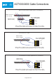


Cable: 8 Core Screened,
Max 30m
Controller
ENTRY/EXIT READER
0 1 2 3 4 5 6 7 8 9
BATCH:
PRODUCT:
SERIAL NUMBER:
98XX-1
ACT20 REV2.1
012345
OP2
OP3
BUZZER
0V
0V
DOOR
CONTACT
PUSH
BUTTON
INTERLOCK
(PB2)
TAMPER
12-24V
AC/DC
+
-
WHITE
GREE
N
BLUE
BROWN
YELLOW
BLACK
RED
ORAN
GE
SENSE
UNUSED
OPTIONAL EXIT READER
ENTRY READER
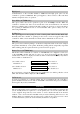
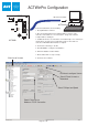
The ACT20 connects in parallel
between the reader and the controller.
An extra line (ORANGE) is used to
bring +12VDC power to the ACT20.
The shields should be joined.
Controller Cable ACT20
Sense White Buzzer
Clock Green OP2
Data Blue OP3
+5V Red
0V Black 0V
Red LED Brown Door Contact
Grn LED Yellow Push Button
+12V Orange +12V
ORANGE
Connect to
12Vdc
Page 24 of 32
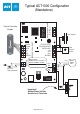
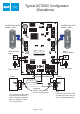
ACT20 PIN Pad Installation Diagram
Technical Manuals Online! - http://www.tech-man.com