
- Guardian Technologies, LLC Portable Generator User Manual

SECTION 4.4
DIAGNOSTIC TESTS
DC CONTROL
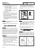
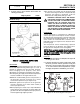
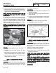
4. A starter motor in good condition will be within the
following specifications:
Single Cylinder V-twin
Minimum rpm 800 4500
Maximum Amps 9 50
Figure 15. Testing Starter Motor Performance
TEST 51 - CHECK FUEL SUPPLY AND
PRESSURE
DISCUSSION:
The air-cooled prepackaged generator was factory
tested and adjusted using natural gas as a fuel. If
desired, LP (propane) gas may be used. However,
when changing over to propane, some minor
adjustments are required. The following facts apply:
❏ An adequate gas supply and sufficient fuel pressure
must be available or the engine will not start.
❏ Minimum recommended gaseous fuel pressure at
the generator fuel inlet connection is 11 inches
water column (6.38 ounces per square inch).
❏ Maximum gaseous fuel pressure at the generator
fuel inlet connection is 14 inches water column (8
ounces per square inch).
❏ When propane gas is used, only a "vapor withdrawal"
system may be used. "This type of system utilizes the
gas that form above the liquid fuel the vapor pressure
must be high enough engine operation.
❏ The gaseous fuel system must be properly tested
for leaks following installation and periodically
thereafter. No leakage is permitted. Leak test
methods must comply strictly with gas codes.
DANGER: GASEOUS FUELS ARE HIGHLY
EXPLOSIVE. DO NOT USE FLAME OR HEAT
TO TEST THE FUEL SYSTEM FOR LEAKS.
NATURAL GAS IS LIGHTER THAN AIR,
TENDS TO SETTLE IN HIGH PLACES. LP
(PROPANE) GAS IS HEAVIER THAN AIR,
TENDS TO SETTLE IN LOW AREAS. EVEN
THE SLIGHTEST SPARK CAN IGNITE THESE
GASES AND CAUSE AN EXPLOSION.
PROCEDURE:
A water manometer or a gauge that is calibrated in
"ounces per square inch" may be used to measure
the fuel pressure. Fuel pressure at the inlet side of the
fuel solenoid valve should be between 11 - 14 inches
water column as measured with a manometer, or
6.38-8.00 ounces per square inch as measure with a
pressure gauge.
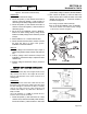
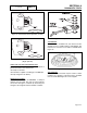
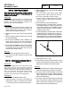
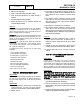
The fuel pressure can be checked using a pressure
tester kit (Generac p/n 0C7977). See Figure 16 for
the gas pressure test point on the fuel regulator.
NOTE:
Where
a
primary
regulator
is
used
to
establish
fuel
inlet
pressure,
adjustment
of
that
regulator
is
usually
the
responsibility
of
the
fuel
supplier
or
the
fuel
supply
system
installer.
RESULTS:
1. If fuel supply and pressure are adequate, but engine will
not start, go on to Test 53.
2. If generator starts but runs rough or lacks power, repeat
the above procedure with the generator running and
under load. The fuel system must be able to maintain
11”-14” water column at all load requirements. If proper
fuel supply and pressure is maintained, go to Test 55.
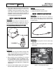
Figure 16. Air Cooled Engine Fuel System
PART 4
Page 4.4-9