ULTRA SOURCE Portable Generator Owner’s Manual • SAFETY • ASSEMBLY • OPERATION • TROUBLESHOOTING • ELECTRICAL DATA • PARTS COMMERCIAL • INDUSTRIAL • RESIDENTIAL • WARRANTY MODEL: 004582-2 AUTHORIZED DEALER SUPPORT: 1-800-333-1322 15,000 Watt Portable Generator
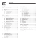
Table of Contents Commercial-Industrial-Residential Portable Generator System Safety Rules .................................................................. 1 Section 3 – Maintenance ........................................... 13 Section 1 – General Information ................................. 4 3.1 Maintenance Schedule ....................................................... 13 1.1 Unpacking ............................................................................. 4 1.1.1 Accessory Box ........
INTRODUCTION Thank you for purchasing this model by Generac Power Systems, Inc. This model is a compact, high performance, air-cooled, engine driven generator designed to supply electrical power to operate electrical loads where no utility power is available or in place of utility due to a power outage. READ THIS MANUAL THOROUGHLY We also strongly recommend instructing other users to properly start and operate the unit. This prepares them if they need to operate the equipment in an emergency.
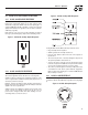
IMPORTANT SAFETY INSTRUCTIONS Commercial-Industrial-Residential Portable Generator System THESE INSTRUCTIONS – The manufacturer suggests that these rules for safe operation be copied and posted near the unit's SAVE installation site. Safety should be stressed to all operators and potential operators of this equipment. • Never start or stop the unit with electrical loads connected to receptacles AND with connected devices turned ON.
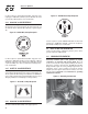
IMPORTANT SAFETY INSTRUCTIONS Commercial-Industrial-Residential Portable Generator System ELECTRICAL HAZARDS EXPLOSION HAZARDS • All generators covered by this manual produce dangerous electrical voltages and can cause fatal electrical shock. Utility power delivers extremely high and dangerous voltages as does the generator when it is in operation. Avoid contact with bare wires, terminals, connections, etc., while the unit is running.
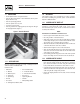
Section 1 – General Information Commercial-Industrial-Residential Portable Generator System 1.1 UNPACKING 1.2 ASSEMBLY • Set the palleted carton on a rigid flat surface. • Remove staples along bottom of carton that fasten carton to pallet. Open carton from top. • Remove all packaging material. • Remove separate accessory box. • Lift carton off the generator. • Remove generator from shipping pallet by removing bolts through the shipping brackets (Figure 1).
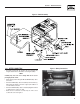
Section 1 - General Information Commercial-Industrial-Residential Portable Generator System Figure 2 - Handle Assembly 1.2.3 BATTERY CONNECTION • The battery shipped with the generator has been provided fully charged. Caution must be taken when connecting the battery. NOTE: Figure 3 - Battery Connections Negative Cable Positive Cable A battery may lose some of it’s charge when not in use for prolonged periods of time. • Cut the tie wrap cable holding the RED and BLACK battery cables to the stator.
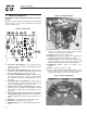
Section 2 – Operation Commercial-Industrial-Residential Portable Generator System Figure 5 - Generator Controls 2.1 KNOW THE GENERATOR Read the Owner’s Manual and Safety Rules before operating this generator. Compare the generator to Figures 4 through 6 to become familiarized with the locations of various controls and adjustments. Save this manual for future reference. 11 7 Figure 4 - Control Panel 12 15 1.
Section 2 – Operation Commercial-Industrial-Residential Portable Generator System 2.2 CORD SETS AND CONNECTION PLUGS Figure 8 - 120 VAC, 20 Amp GFCI Receptacle 2.2.1 120 VAC, 20 AMP, DUPLEX RECEPTACLE This is a 120 Volt outlet protected against overload by a 20 Amp push-to-reset circuit breaker (Figure 7). Use each socket to power 120 Volt AC, single phase, 60 Hz electrical loads requiring up to a combined 2400 watts (2.4 kW) or 20 Amps of current.
Section 2 – Operation Commercial-Industrial-Residential Portable Generator System Use this receptacle to operate 120 Volt AC, 60 Hz, single phase loads requiring up to 3600 watts (3.6 kW) of power at 30 Amps. The outlet is protected by a 30 Amp push-to-reset circuit breaker. Figure 12 - 120/240 VAC, 50 Amp Receptacle 2.2.4 120/240 VAC, 30 AMP RECEPTACLE Use a NEMA L14-30 plug with this receptacle. Connect a suitable 4wire grounded cord set to the plug and to the desired load.
Section 2 – Operation Commercial-Industrial-Residential Portable Generator System Proper grounding of the generator will help prevent electrical shock in the event of a ground fault condition in the generator or in connected electrical devices. Proper grounding also helps dissipate static electricity, which often builds up in ungrounded devices. 2.3.2 CONNECTING ELECTRICAL LOADS DO NOT connect 240 Volt loads to 120 Volt receptacles. DO NOT connect 3-phase loads to the generator.
Section 2 – Operation Commercial-Industrial-Residential Portable Generator System 2.6 BEFORE STARTING THE GENERATOR 2.6.2 ADDING GASOLINE Prior to operating the generator, engine oil and gasoline will need to be added, as follows: fill fuel tank indoors. Never fill fuel tank Never when engine is running or hot. DO NOT light a 2.6.1 ADDING ENGINE OIL cigarette or smoke when filling the fuel tank.
Section 2 – Operation Commercial-Industrial-Residential Portable Generator System 2.7 TO START THE ENGINE • Move engine CHOKE knob outward to “Full Choke” position (Figure 17). Figure 17 - Full Choke Position Never start or stop engine with electrical devices plugged into the receptacles AND devices turned on. • Unplug all electrical loads from the unit's receptacles before starting the engine. • Make sure the unit is in a level position. • Open the fuel shut-off valve (Figure 15).
Section 2 – Operation Commercial-Industrial-Residential Portable Generator System 2.9 AUTOMATIC IDLE CONTROL This feature is designed to greatly improve fuel economy. When this switch is turned “On,” the engine will only run at its normal fast governed engine speed when electrical load is connected. When the load is removed, the engine will run at a reduced speed of 2100 RPM. With the switch “Off,” the engine runs at the normal fast engine speed all the time.
Section 3 — Maintenance Commercial-Industrial-Residential Portable Generator System 3.1 MAINTENANCE SCHEDULE Follow the calendar intervals. More frequent service is required when operating in adverse conditions noted below.
Section 3 — Maintenance Commercial-Industrial-Residential Portable Generator System 3.3 GENERAL RECOMMENDATIONS The warranty of the generator does not cover items that have been subjected to operator abuse or negligence. To receive full value from the warranty, the operator must maintain the generator as instructed in this manual. Some adjustments will need to be made periodically to properly maintain the generator.
Section 3 — Maintenance Commercial-Industrial-Residential Portable Generator System 3.3.6 REPLACING THE SPARK PLUG To clean or replace foam pre-cleaner: Use Champion RC14YC spark plug or equivalent. The correct air gap is 1.01 mm (0.040 in.) (Figure 18). Replace the plug once each year. This will help the engine start easier and run better. • Remove air cleaner cover, then foam pre-filter. • Wash pre-cleaner in soapy water. Squeeze pre-filter dry in clean cloth (DO NOT TWIST).
Section 3 — Maintenance Commercial-Industrial-Residential Portable Generator System 3.6 ADJUSTING VALVE CLEARANCE Figure 21 - Valve Clearance Adjustment After the first 50 hours of operation, check the valve clearance in the engine and adjust if necessary. Important: If feeling uncomfortable about doing this procedure or the proper tools are not available, please take the generator to the nearest service center to have the valve clearance adjusted.
Section 3 — Maintenance Commercial-Industrial-Residential Portable Generator System 3.8 LONG TERM STORAGE 3.9 OTHER STORAGE TIPS: It is important to prevent gum deposits from forming in essential fuel system parts such as the carburetor, fuel hose or tank during storage. Also, experience indicates that alcohol-blended fuels (called gasohol, ethanol or methanol) can attract moisture, which leads to separation and formation of acids during storage.
Section 4 — Troubleshooting Commercial-Industrial-Residential Portable Generator System 4.1 TROUBLESHOOTING GUIDE PROBLEM CAUSE CORRECTION Engine is running, but no AC output is available. 1. 2. 3. 4. Circuit breaker is open. Poor connection or defective cord set. Connected device is bad. Fault in generator. 1. 2. 3. 4. Reset circuit breaker. Check and repair. Connect another device that is in good condition. Contact Authorized Service Facility.
Section 5 — Electrical Data Electrical Schematic – Drawing No.
Section 5 — Electrical Data Wiring Diagram – Drawing No.
Section 5 — Electrical Data Wiring Diagram – Drawing No.
Section 6 — Exploded Views and Parts Lists Handle, Frame & Wheel Kit – Drawing No.
Section 6 — Exploded Views and Parts Lists Handle, Frame & Wheel Kit – Drawing No. 0E0695-B ITEM 1 2 3 4 5 6 7 8 9 10 11 12 13 14 15 16 17 18 19 20 21 22 23 24 25 26 27 28 29 30 31 32 33 34 35 36 37 38 39 40 41 42 43 44 45 46 47 48 49 50 51 52 PART NO. QTY.
Section 6 — Exploded Views and Parts Lists Control Panel – Drawing No.
Section 6 — Exploded Views and Parts Lists Control Panel – Drawing No. 0G0727-B ITEM PART NO. QTY.
Section 6 — Exploded Views and Parts Lists Generator – Drawing No.
Section 6 — Exploded Views and Parts Lists Generator – Drawing No. 0G0742-A ITEM PART NO. QTY.
Section 6 — Exploded Views and Parts Lists GT-760/990 Engine – Drawing No.
Section 6 — Exploded Views and Parts Lists GT-760/990 Engine – Drawing No. 0E8589-W - Part 1 ITEM PART NO. QTY.
Section 6 — Exploded Views and Parts Lists GT-760/990 Engine – Drawing No.
Section 6 — Exploded Views and Parts Lists GT-760/990 Engine – Drawing No. 0E8589-W - Part 2 ITEM PART NO. QTY.
Section 7 – Warranty Commercial-Industrial-Residential Portable Generator System CALIFORNIA EMISSION CONTROL WARRANTY STATEMENT YOUR WARRANTY RIGHTS AND OBLIGATIONS The California Air Resources Board (CARB) and Generac Power Systems, Inc. (Generac) are pleased to explain the Emission Control System warranty on your new engine. In California, new off-road Large Spark-Ignition (LSI) engines must be designed, built and equipped to meet the state's stringent anti-smog standards.
Section 7 – Warranty Commercial-Industrial-Residential Portable Generator System EMISSION CONTROL SYSTEM WARRANTY Emission Control System Warranty (ECS warranty) for 2001 and later model year LSI engines: (a) Applicability: This warranty shall apply to 2001 and later model year engines. The ECS Warranty period shall begin on the date the new engine or equipment is purchased by/delivered to its original, end-use purchaser/owner and shall continue for 24 consecutive months thereafter.
Section 7 – Warranty Commercial-Industrial-Residential Portable Generator System GENERAC POWER SYSTEMS “TWO YEAR” LIMITED WARRANTY FOR GUARDIAN® “15,000 WATT PORTABLE GENERATOR” For a period of two years from the date of original sale, Generac Power Systems, Inc. (Generac) warrants its Guardian generator will be free from defects in materials and workmanship for the items and period set forth below.