
User's Manual

Signpost – Installation Manual and User Guide
Guard RFID Solutions Inc. Page 3 of 7
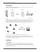
Due to a nature of RF communication, it is hard to predict communication range between a Tag and a Tag
Reader. This is heavily dependent on surrounding ambient, architecture, even people and equipment
movement. However, in order to install the system, the assumption of certain communication range has to
be made. To achieve complete RF coverage of a typical office style area (including typical healthcare
facility), good starting point is to position Tag Readers in a grid pattern with 25-foot centers. During
system testing this assumption may need some adjusting (accomplished by moving Tag Readers in either
direction), but in majority of cases, it is proven to be a good general rule of thumb.
Locations in which Tag Reader is shielded by metal tiles or walls should be avoided, or density of Tag
Readers should be increased.
Wiring
Tag Reader requires 3 types of wiring to be fully functional:
- Power Supply:
o 12VDC power supply which is capable of delivering 0.3A of continuous current. AWG-
18 or heavier wire should be used (depending on wire length).
- Networking:
o Ethernet CAT-5 cable with RJ-45 should be used for communication between a Tag
Reader and the Server.
- Peripheral:
o This is applicable To Tag Reader DC only. It includes wiring for Door Switch Input,
Bypass Input and Relay Output. Door Switch and Bypass Inputs can use AWG-20 or
heavier wire, but Relay Output should use AWG-18 or heavier wire.
All Tag Reader’s wiring connections are accessible without opening the enclosure.
Configuration
Tag Reader configuration is accomplished via 3-position DIP switch located inside the enclosure.
The functionality of these switches is as follows:
- Switch 1: Communication to Host disabled.
o “0” Æ Communication enabled
o “1” Æ Communication disabled
- Switch 2: Mode of alarm operation
o “0” Æ Continuous Alarm (Tag Reader will continue alarming after the Tag has left
Signpost field until the alarm is acknowledged by Bypass)
o “1” ÆNon-Continuous Alarm (Tag Reader will stop alarming when the tag leaves the
Signpost field)
- Switch 3: Alarm Buzzer enabled
o “0” Æ Alarm Buzzer disabled
o “1” Æ Alarm Buzzer enabled