
Operation Manual
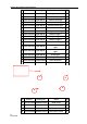
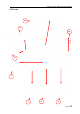

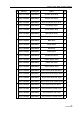

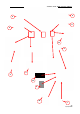
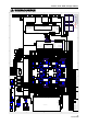
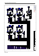
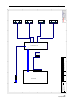
Table Of Contents

Treasure Dome RFID Prototype Manual
11/15/2019
37
10. WIRING DIAGRAM
1
1
2
2
3
3
4
4
5
5
6
6
7
7
8
8
D D
C C
B B
A A
Name
Ver Size
Date
Path
A2
=CurrentDate
=DocumentFullPathAndName
UNIS
14
13
1
2
12
3
11
4
10
5
9
6
8
7
15
16
A2547HA 16P
14
13
1
2
12
3
11
4
10
5
9
6
8
7
15
16
?
A2547HA 16P
1
2
3
4
5
6
VH-6A
1
2
3
VH-3A
1
2
3
4
5
6
7
XH-7A
1P coin mechanism
1P button
1P Service button
1P reset button
Tilt alarm R
2P coin mechanism
2P button
2P Service button
2P reset button
3P coin mechanism
3P button
3P Service button
3P reset button
4P coin mechanism
4P button
4P Service button
4P reset button
J1
J7
J3
J7
1
2
3
4
5
6
7
8
?
XH-8A
1P Coin mechanism GND
2P Coin mechanism GND
3P Coin mechanism GND
4P Coin mechanism GND
1P coin counter
2P coin counter
3P coin counter
4P coin counter
1P button light
2P button light
3P button light
4P button light
+12V
+12V
GND
GND
Display SI
DisplayRCK
Display SCK
70
C0
10
J6
J10
J13
10
30
80
1
2
VH-2A
1
2
VH-2A
J17
J16
10
18
10
18
ZYKJ_2016.PCB V2.1
KZ2016_IN.PCB V1.0
14
13
1
2
12
3
11
4
10
5
9
6
8
7
15
16
A2547HA 16P
14
13
1
2
12
3
11
4
10
5
9
6
8
7
15
16
A2547HA 16P
1
2
3
4
5
6
VH-6A
1P Claw depth SW
1P Claw upper sensor
1P Claw bottom sensor
1P BOUNS sensor
J1
J7
J2
J3
J1'
1P lift motor A
1P lift motor B
1P Claw motor A
1P Claw motor B
1
2
3
4
5
6
7
8
VH-8A
1
2
3
4
5
6
7
8
XH-8A
1
2
3
4
5
6
7
8
9
10
XH-10A
+12V
+12V
GND
GND
1
2
3
4
5
6
7
8
XH-8A
J13
J10
J2
1
2
3
4
5
6
7
XH-7A
J5
2P Claw depth SW
2P Claw upper sensor
2P Claw bottom sensor
2P BOUNS sensor
3P Claw depth SW
3P Claw upper sensor
3P Claw bottom sensor
3P BOUNS sensor
4P Claw depth SW
4P Claw upper sensor
4P Claw bottom sensor
4P BOUNS sensor
Truntable zero sensor
2P lift motor A
2P lift motor B
2P Claw motor A
2P Claw motor B
3P lift motor A
3P lift motor B
3P Claw motor A
3P Claw motor B
4P lift motor A
1
2
3
VH-3A
4P lift motor B
4P Claw motor A
4P Claw motor B
BOUNS support rod motor A
BOUNS support rod motor B
1#Eye light
2#Eye light
3#Eye light
4#Eye light
Stepping motor EN
1#Light
2#Light
3#Light
4#Light
GND
Light ring SCK
Light ring RCK
Light ring S
Stepping motor PUL
C0N
10N
70N
40N
20N
D0N
90N
50N
C5N
15N
75N
35N
45N
25N
D5N
95N
A0N
25
D5
C0
10
70
40
50
20
C5
15
70
40
D5
25
95
45
D0
20
90
50
C0
10
70
40
C5
15
75
35
ZYKJ_2016.PCB V2.2
12V
5V
C0
10
70
80
30
KZ2016.PCB V1.0
1
2
3
4
5
6
7
XH-7A
TXD
RXD
Connect GND
20
40
80
J5
GND
B
A
-
+
-
+
1
2
3
4
5
6
7
8
9
XH-9A
GND
B
A
14
13
1
2
12
3
11
4
10
5
9
6
8
7
15
16
17
18
19
20
21
22
23
24
25
26
A2547HA 26P
J20
1
2
3
4
5
6
7
8
9
10
VH-10A
1
2
3
4
5
6
7
8
9
10
11
VH-11A
1
2
3
4
5
6
7
8
9
VH-9A
J21
J22
J23
XS_BONUS_CEC.PCB V1.0
1
2
3
4
5
6
7
VH-7A
1
2
3
4
5
6
VH-6A
5V
12V
GND
Light ring SCK
Light ring RCK
Light ring S
5V
12V
GND
Light ring SCK
Light ring RCK
Light ring S
4#Light ring
XS_BONUS_CEC.PCB V1.0
1
2
3
4
5
6
7
VH-7A
1
2
3
4
5
6
VH-6A
5V
12V
GND
Light ring SCK
Light ring RCK
Light ring S
5V
12V
GND
Light ring SCK
Light ring RCK
Light ring S
3#Light ring
XS_BONUS_CEC.PCB V1.0
1
2
3
4
5
6
7
VH-7A
1
2
3
4
5
6
VH-6A
5V
12V
GND
Light ring SCK
Light ring RCK
Light ring S
5V
12V
GND
Light ri ng SCK
Light ring RCK
Light ring S
1#Light ring
XS_BONUS_CEC.PCB V1.0
1
2
3
4
5
6
7
VH-7A
1
2
3
4
5
6
VH-6A
5V
12V
GND
Light ring SCK
Light ring RCK
Light ring S
5V
12V
GND
Light ring SCK
Light ring RCK
Light ri ng S
2#Light ring
C0
10
70
80
13
30
C0
10
70
80
13
30
C0
10
70
80
13
30
C0
10
70
80
13
30
C0
10
70
80
13
30
C0
10
70
80
13
30
1
2
3
4
5
6
P
C0
10
70
80
13
30
C0
10
70
80
13
30
1
2
3
4
5
6
7
8
9
10
11
12
13
14
15
16
C
13
13
13
13
13
13
13
13
80
80
80
80
80
80
80
80
30
30
80
80
30
30
30
30
1
2
3
4
5
6
7
8
9
10
11
12
13
14
C
80
80
80
80
1
2
3
4
5
6
C?
80
80
80
D0
D0
D0
1
2
3
4
5
6
7
8
9
10
11
12
13
14
15
16
17
18
C
C0N
10N
70N
40N
20N
D0N
90N
50N
C5N
15N
75N
35N
45N
25N
D5N
95N
A0N
1
2
3
4
5
6
7
8
9
10
11
12
C
D0
20
90
50
C0
10
70
40
D5
25
95
45
1
2
3
4
5
6
7
8
9
10
C
50
20
C5
15
70
40
C5
15
75
35
1
2
3
4
C
C0
10
70
40
1
2
3
4
5
6
C
25
D5
C5
15
75
45
1
2
3
4
5
6
XH-6A
1
2
3
4
5
6
7
?
XH-7A
SMG10106-3W.PCB V3.1
5V
GND
RCK
SCK
S
5V
GND
RCK
SCK
S
1
2
3
4
5
6
XH-6A
1
2
3
4
5
6
7
XH-7A
SMG10106-3W.PCB V3.1
5V
GND
RCK
SCK
S
5V
GND
RCK
SCK
S
C0
10
70
80
13
C0
10
70
80
13
13
80
C0
10
70
1
2
3
4
5
6
7
8
C4201-8A
1#Ticket reset
2# Ticket reset
3#Ticket reset
4#Ticket reset
1#Gate motor initial
2#Gate motor initial
3#Gate motor initial
4#Gate motor initial
3# Ticket feedback
4#Ticket feedback
Switch DIP1
Switch DIP2
Switch DIP3
Switch DIP4
Switch DIP5
Switch DIP6
Switch DIP7
Switch DIP8
1#Gate motor A
2#Gate motor A
3#Gate motor A
4#Gate motor A
1#Truntable motor
2#Truntable motor
3#Truntable motor
4#Truntable motor
1# Ticket meter
2# Ticket meter
3# Ticket meter
4# Ticket meter
3# TIcket drive
4# TIcket drive
1# Out of tik light
2# Out of tik light
3# Out of tik light
4# Out of tik light
2#Ticket feedback
1#Ticket feedback
2# TIcket drive
1# TIcket drive
1
2
3
4
VH-4A
1
2
3
4
XH-4A
J1
J14
M3-MB.PCB V1.1
DI
GND
+12V
1#Outside line breath light
DI
GND
+12V
2#Outside line breath light
DI
GND
+12V
3#Outside line breath light
DI
GND
+12V
4#Outside line breath light
1
2
3
P
1
2
3
C
30
80
20
1
2
3
P
1
2
3
C
30
80
20
1
2
3
P
1
2
3
C
30
80
20
1
2
3
P
1
2
3
C
30
80
20
30
80
20
30
80
20
30
80
20
30
80
20
DI
GND
+12V
DI
GND
+12V
DI
GND
+12V
Bottom breath light
Breath light
Outside breath light
1
2
3
P
1
2
3
C
30
80
20
1
2
3
P
1
2
3
C
30
80
20
1
2
3
P
1
2
3
C
30
80
20
30
80
20
30
80
20
30
80
20
DI
GND
+12V
Inside breath light
1
2
3
C
1
2
3
P
30
80
20
30
80
20
DI
GND
+12V
Marquee breath light
GND
+12V
Marquee upper white light
GND
+12V
Marquee bottom white light
1
2
3
4
5
6
7
8
P
30
30
30
80
80
80
20
30
30
30
80
80
80
20
1
2
3
C
1
2
3
P
1
2
C
1
2
P
1
2
C
1
2
P
30
30
30
80
80
80
20
DI
GND
+12V
Marquee breath light
30
80
20
1
2
3
C
1
2
3
P
30
80
20
GND
+12V
Marquee inside light
30
80
1
2
C
1
2
P
30
80
GND
SDO
VDD
GND
VDD
XXH-150703A
VH-3P
3
2
1
VH-2P
2
1
Marquee control panel
Fan Fan
1
2
P
1
2
C
1
2
P
1
2
C
8080
8080
30 10
1030
1
2
C
1
2
P
10
18
10
18
1
2
C
1
2
P
10
18
1#speaker
2# speaker
10
18
M
Support rod A
M
Support rod B
1
2
P
C4201-2A
1
2
C
1
2
P
C4201-2A
1
2
C
80
10
80
10
D5
80
D5
80
Toggle switch
D5
80
D0
D0
80
80
L
N
E
+12V
GND
+12V
GND
NES-350-12
12V/12.5A
L
N
E
+24V
GND
+24V
GND
NES-150-24
24V/6.5A
L
N
E
+5V
GND
+5V
GND
NES-150-5
5V/12.5A
C0K
43U
20K
C0K
43U
20K
C0K
43U
20K
80
30
30
80
80
D0
80K
D0
80
80
13
13
80
YB11C9-10A-Q
1
2
3
C
C0K
43U
20K
FILTER
YB41D6-6A-Q
1
2
3
P
C0K
43U
20K
C0K
43U
20K
FILTER
1
2
3
C
C
C0K
43U
20K
Mn-Zn green ring
EG32AC
1
2
3
P
C0K
43U
20K
1
2
3
C
C0K
43U
20K
RCCB
Breaker
NO
NO
COM2
COM1
1
2
3
P
1
2
3
C
C0K
43U
20K
C0K
43U
20K
A
POWER-PLUG
Power adapter
12V/5A
1
2
3
4
C
1
2
3
4
P
30
80
30
80
35x2
35x2
85x2
85x2
1
2
3
P
C0K
43U
20K
A
POWER-PLUG
Power adapter
12V/5A
1#Gate motor B
2#Gate motor B
3#Gate motor B
4#Gate motor B
1#Gate motor M
2#Gate motor M
3#Gate motor M
4#Gate motor M
888888
888888
1
2
3
4
5
6
7
8
P
Service
Reset
Ticket reset
90N
90N1
90N
90N2
C0
10
70
80
90N
70
10
C0
90N1
90N2
80
1#Ticket counter
1#Coin counter
M
1#Gate motor
1
2
P
80
30
1#button
1# Coin mechanism
TL131
1
2
3
P
10
80
50
1P Out of tik light
1
2
P
30
C5030HF-3*3P
1#DBV port
1
2
6
C0N
35
85
8
9
Spring 4.8
Spring 6.3
80
C4140HM-3*3P
1#DBV port
4
6
7
C0N*2
80*2
8
1
2
C
1
2
3
C
1
2
C
C0K
20K
20N
45
38*2
70
38*2
10
C0N*2
1
2
3
4
5
6
VH-6A
1
2
3
4
VH-4A
DJQDL6205.PCB V1.0
A1
A2
B1
B2
GND
VCC
B-
B+
A-
A+
10
C0
1
2
3
4
5
6
P
1#Gate motor initial
Spring4.8
70N
80
1#Gate motor M
Spring 4.8
40N
80
10
C0
30
80
1#Motor control board
30
80*3
10
C0
70N
40N
C0K
20K
38
80
35
85
888888
888888
1
2
3
4
5
6
7
8
P
Service
Reset
Ticket reset
90N
90N1
90N
90N2
C0
10
70
80
90N
70
10
C0
90N1
90N2
80
2#Ticket counter
2#Coin counter
M
Gate motor
1
2
P
80
30
2#Button
2# Coin mechanism
TL131
1
2
3
P
10
80
50
1
2
3
4
VH-4A
2# Ticket converted board
80
38
45*2
20N*2
2P Out of tik light
1
2
P
30
C5030HF-3*3P
2#DBV port
1
2
6
C5N
35
85
8
9
Spring 4.8
Spring6.3
80
C4140HM-3*3P
2# DBV port
4
6
7
C5N*2
80*2
8
1
2
C
1
2
3
C
1
2
C
C0K
20K
20N
45
38*2
70
38*2
70
C5N*2
1
2
3
4
5
6
VH-6A
1
2
3
4
VH-4A
DJQDL6205.PCB V1.0
A1
A2
B1
B2
GND
VCC
B-
B+
A-
A+
10
C0
1
2
3
4
5
6
P
2#Gate motor initial
Spring 4.8
70N
80
2#Gate motor M
Spring 4.8
40N
80
10
C0
30
80
2#Motor control board
30
80*3
10
C0
70N
40N
C0K
20K
38
80
35
85
888888
888888
1
2
3
4
5
6
7
8
P
Service
Reset
Ticket reset
90N
90N1
90N
90N2
C0
10
70
80
90N
70
10
C0
90N1
90N2
80
4#TIcket counter
4#Coin counter
M
4#Gate motor
1
2
P
80
30
4#Button
4# Coin mechanism
TL131
1
2
3
P
10
80
50
4P Out of tik light
1
2
P
30
C5030HF-3*3P
4#DBV port
1
2
6
15N
35
85
8
9
Spring 4.8
Spring 6.3
80
C4140HM-3*3P
4#DBV port
4
6
7
15N*2
80*2
8
1
2
C
1
2
3
C
1
2
C
C0K
20K
20N
45
3C*2
70
3C*2
15N
1
2
3
4
5
6
VH-6A
1
2
3
4
VH-4A
DJQDL6205.PCB V1.0
A1
A2
B1
B2
GND
VCC
B-
B+
A-
A+
10
C0
1
2
3
4
5
6
P
4#Gate motor initial
Spring 4.8
70N
80
4#Gate motor M
Spring 4.8
40N
80
10
C0
30
80
4#Motor control board
30
80*3
10
C0
70N
40N
C0K
20K
3C
80
35
85
888888
888888
1
2
3
4
5
6
7
8
P
Service
Reset
Ticket reset
90N
90N1
90N
90N2
C0
10
70
80
90N
70
10
C0
90N1
90N2
80
3#Ticket counter
3#Coin counter
M
1#Gate motor
1
2
P
80
30
3#Button
3# Coin mechanism
TL131
1
2
3
P
10
80
50
3P Out of tik light
1
2
P
30
C5030HF-3*3P
3#DBV port
1
2
6
10N
35
85
8
9
Spring4.8
Spring6.3
80
C4140HM-3*3P
3# DBV port
4
6
7
10N*2
80*2
8
1
2
C
1
2
3
C
1
2
C
C0K
20K
20N
45
3C*2
70
3C*2
1
2
3
4
5
6
VH-6A
1
2
3
4
VH-4A
DJQDL6205.PCB V1.0
A1
A2
B1
B2
GND
VCC
B-
B+
A-
A+
10
C0
1
2
3
4
5
6
P
3#Gate motor initial
Spring 4.8
70N
80
3#Gate motor M
Spring 4.8
40N
80
10
C0
30
80
3#Motor control board
30
80*3
10
C0
70N
40N
C0K
20K
3C
80
35
85
80K
1
2
3
4
5
6
1
2
3
4
5
6
30K
30K
30K
30K
30K
30K
FUSE-6A.PCB V1.1
1#Display1#Display
C0N
10N
70N
40N
20N
C5N
15N
25N
95N
10N
70N
20N
90N
15N
75N
45N
95N
1
2
3
4
5
6
7
8
C
1
2
3
4
5
6
C
45N
95N
75N
15N
10
70
40
20
20
1
2
3
4
5
6
7
8
C
1
2
3
4
5
6
C
20N
90N
40
10N
10N
90
50
C5
15
75
45
25
95
95
40
20
C5
3C
80
3C
80
3C
80
70N
95
3C
80
95
3C
80
3C
80
38
80
38
80
1
2
3
4
5
6
C
1
2
3
4
5
6
C
1
2
3
4
5
6
7
8
C
1
2
3
4
5
6
7
8
C
38
80
38
80
38
80
38
80
70
10
C5N
C0N
50
90
45
75
70N
40N
25N
95N
10N
15N
C5N
C0N
15N
10N
20N
90N
50N
C5N
15N
75N
45N
25N
95N
50N
C0N
10N
70N
40N
20N
90N
50N
A0N
C0
10
70
40
20
90
50
C5
15
75
45
25
95
50
C0
10
C0
10
70
40
20
90
50N
45
25N
95
15
95
15N
C5N
C0
20N
25N
45
70
50
10
C0N
75N
75
90N
40
50N
45
20
90
10
C0
45
25
C0
10
70
40
50N
C5N
25N
10N
45N
15N
95N
50N
C0
10
70
80
13
C0
10
70
80
13
1
2
3
4
5
6
XH-6A
1
2
3
4
5
6
7
XH-7A
SMG10106-3W.PCB V3.1
5V
GND
RCK
SCK
S
5V
GND
RCK
SCK
S
1
2
3
4
5
6
XH-6A
1
2
3
4
5
6
7
XH-7A
SMG10106-3W.PCB V3.1
5V
GND
RCK
SCK
S
5V
GND
RCK
SCK
S
C0
10
70
80
13
C0
10
70
80
13
13
80
C0
10
70
1
2
3
4
5
6
XH-6A
1
2
3
4
5
6
7
XH-7A
SMG10106-3W.PCB V3.1
5V
GND
RCK
SCK
S
5V
GND
RCK
SCK
S
1
2
3
4
5
6
XH-6A
1
2
3
4
5
6
7
XH-7A
SMG10106-3W.PCB V3.1
5V
GND
RCK
SCK
S
5V
GND
RCK
SCK
S
C0
10
70
80
13
C0
10
70
80
13
13
80
C0
10
70
C0
10
70
80
13
C0
10
70
80
13
1
2
3
4
5
6
XH-6A
1
2
3
4
5
6
7
XH-7A
SMG10106-3W.PCB V3.1
5V
GND
RCK
SCK
S
5V
GND
RCK
SCK
S
1
2
3
4
5
6
XH-6A
1
2
3
4
5
6
7
XH-7A
SMG10106-3W.PCB V3.1
5V
GND
RCK
SCK
S
5V
GND
RCK
SCK
S
C0
10
70
80
13
C0
10
70
80
13
13
80
C0
10
70
C0
10
70
80
13
C0
10
70
80
13
2#Display2#Display
3#Display3#Dis play
4#Display4#Display
13
GND
5V
80
13
10
30
80
1
2
3
4
5
6
C
C0
10
70
80
30
13
M
Turntable motor
~
1
2
3
P
C0K
43U
20K
1
2
3
C
30
30
38
38
3C
3C
C0K
43U
20K
+12V
+12V
GND
GND
30
80
30
80
30
80
30
80
80
30
30
80
20
1
2
3
4
5
6
7
8
C
30
30
30
80
80
80
20
Anti-shake weight
20N
80
J21
1
2
3
4
VH-4A
1
2
3
4
5030HM/4A
2# Ticket dispen ser
38
80
45
20N
1
2
3
4
VH-4A
3# Ticket converted board
80
3C
45*2
20N*2
1
2
3
4
VH-4A
1
2
3
4
5030HM/4A
3# Ticket dispenser
3C
80
45
20N
1
2
3
4
VH-4A
1# Ticket converte d board
80
38
45*2
20N*2
1
2
3
4
VH-4A
1
2
3
4
5030HM/4A
1#icket dispenser
38
80
45
20N
1
2
3
4
VH-4A
4# Ticket convert ed board
80
3C
45*2
20N*2
1
2
3
4
VH-4A
1
2
3
4
5030HM/4A
4# Ticket dispenser
3C
80
45
20N
B
U AWG 16 UL1015
N
K
F
L
AWG 18 UL1015
AWG 20 UL1007
AWG 22 UL1007
AWG 24 UL1007
WIRE SPECIFICATION CODE
1
2
3
4
5
PINK
7
8
9
A
B
C
D
EGREY
RED
BLUE
YELLOW
GREEN
WHITE
ORANGE
BLACK
CELESTE
BROWN
PURPLE
AQUA
SHIELD
WIRE COLOR CODE
WIRE COLOR:"10" RED
WIRE SPECIFICATION:"K"AWG18 UL1015
IF NO REMARK THE WIRE SPECIFICATION,
THE TABLE REPLACED BY THE CODE,SUCH AS "10" "K"
REMARK:THE WIRE COLOR AND WIRE SPECIFICATION ARE ON
THE DEFAULT IS "AWG22 UL1007"
TICKET DOME
Note: connector type is not indicated in the diagram.
C4201HM for the Yangtze River connector Co., Ltd. C;
C4201HF for the Yangtze River connector Co., Ltd. P;
Ticket Dome Wiring Diagram 1
XSLPJ-PX-00 1/3