
Operation Manual
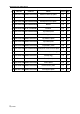
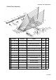
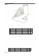

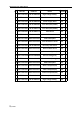
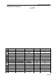
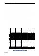
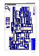
Table Of Contents

Basketball Elite GMP Manual
12/7/2020
39
10. WIRING DIAGRAM
1
1
2
2
3
3
4
4
5
5
6
6
7
7
8
8
D D
C C
B B
A A
UNIS
Universal Space
Amusement machin e
Name:
Size:
Date:
路径
:
Ver.:
A3
=CurrentDate
1
2
3
4
5
6
7
8
9
A
B
C
D
E
F
G
H
I
brown
red
orange
yellow
green
blue
violet
grey
white
black
pink
light green
sky blue
shield layer
J
K
L
M
N
O
P
Q
AWG30 UL1007
AWG28 UL1007
AWG26 UL1007
AWG24 UL1007
AWG22 UL1007
AWG20 UL1007
AWG18 UL1007
AWG16 UL1007
Note: Wire color and wire size is shown in code.
Wire color code
Wire size code
Tolerance
unit mm
scale
:
0~1000
1001~2000
2001~3000
3001~4000
4001~5000
±10
±20
±30
±40
±50
j
k
L
m
n
o
p
q
r
AWG30 UL1015
AWG28 UL1015
AWG26 UL1015
AWG24 UL1015
AWG22 UL1015
AWG20 UL1015
AWG18 UL1015
AWG16 UL1015
AWG14 UL1015
Wire size code
Example 2 0 m
Color of the wire: 20 means red
Size of the wire: m means AWG24 UL1015
JYLQ-PX-00D
Basketball Elite Wiring Diagram
V1.0
AC power cord
PLUG
S1
3
2
1
J01
HM
3
2
1
HF
FUSE
滤波器
NE L
45Q
60P
10P
60P
10P 10P
60P
45Q
45Qx2
Power supply
60P
10P
Network port
45Q
60P
10P
PVC pipe
U6-MB.PCB(
V1.1)
1
2
3
4
J1
+12V
+12V
GND
GND3
2
1
4
VH
U6 mainboard
main board
49" monitor
AC port 3.5 audio port
DVI port
L
J2
RCA(white)
R
RCA(red)
2
1
VH
Amplifier
A1.PCB
2
1
12V
GND
20M
Camera
Port
11
Note:
Front
Back
Left Right
Upper
Monitor side light
Bottom
Middle
(3500mm)
(790mm)
2
1
J5
R+
R-2
1
VH
SPK1
Speaker
2
1
24V
GND
2
1
24V
GND
GND
+12V
SN3
2
1
3
2
1
J11
A2501HM
3
2
1
XH
24
A0
20M
10
60
A0
10
60
A0
A
E
Up
Down
Push Rod rocket SW
20P
A0P
20P
A0P
2
1
J04
HM
2
1
HF
20P
A0P
20P
A0P
2
1
J05
HM
2
1
HF
2x0.3 2 cable
3
2
1
P
S2
Electrical Push Rod rocket SW
F7
fuse
3
2
1
4
J03
HM
3
2
1
4
HF
20P 20P
A0P A0P
F8 fuse
20P 20P
A0P A0P
20P
30P
20P
30P
⑤
②
④
⑥
③
①
3
2
1
4
5
6
J02
HM
3
2
1
4
5
6
HF
20Px2
30Px2
80P
80P
A0P
A0P
1
2
3
4
5
6
7
8
9
J8
3
2
1
4
5
6
7
8
9
VH
Pin:80P①
Pin:20P②
Pin:A0P③
Pin:A0P④
Pin:30P⑤
Pin:80P⑥
Light strip position
20Px2
30Px2
80P
80P
A0P
A0P
20P
30P
80P
A0P
A0P
80P
N
L
E
24V Power supply
24V
GND
80Px2
A0Px2
N
L
E
12V Power supply
12V
GND
24V
GND
2
1
20
J7
2
1
20
YY1820D-20P
3
2
1
4
5
6
7
8
9
J3
3
2
1
4
5
6
7
8
9
XH
+12V
GND
GND
GND
GND
+12V
3
2
1
J14
C
24
A0
2
1
C
2
1
J10
P
46P
A0P
10
60
2
1
J1
DC+
DC-
BOE
Note: F1-F8 are both 5A fuse
Port
DC-12V
A0P
A9
A0
3
2
1
4
J15
+5V
GND
RX
TX3
2
1
4
XH
F3
F2
F1
F4
F2
F3
F4
F1
F2
F3
F4
FUSE BOARD 02
(V1.0)
CN1 CN2
F1
12V
40Px2 40P
40P
40Px2 40P
40P
GND
A0Px2
12V
10
20
30
6x0.3 2 cable
40Px2
41P
42P
46P+64
42P
41P
40P
3
2
1
4
CN2
+5V
GND
RX
TX
3
2
1
4
XH
3
2
1
4
5
J14
3
2
1
J16
+5V
GND
GND
TX
RX
3
2
1
4
5
XH
3
2
1
XH
Bottom metal GND
45Q
Monitor frame GND
45Q
A0P
3
2
1
4
5
6
P
3
2
1
4
5
6
J13
C
20M
40M
90M
E
20M
40M
90M
E
K1 Up
K2 Down
Network port
40
50
2
1
J06
HM
2
1
HF
20P
30P
(Relay )①
(Relay )②
(Relay )③
(Relay )④
(Relay )⑤
(Relay )⑥
(Realy )⑦(Relay )⑧
20P
30P
20Px2
30Px2
80Px2
A0Px2
20P
30P
A0P
80P
A0P
80P
60
70
24
24
10
30
B0
60
70
10
20
30
24
24x2
24x2
60
70
3
2
1
J07
C
3
2
1
P
(shield wire)
3
2
1
4
UART
3
2
1
4
PH
3V3
GND
TX
RX
A0M
40M
90M
2
1
J4
L+
L-2
1
VH
SPK2
Speaker
2
1
P
2
1
J15
C
2
1
12V
GND
2
1
12V
GND
N
L
E
45Qx2
60P
10P
Flexible cable
3
2
1
J09
HM
3
2
1
HF
45Q
60P
10P
2x0.3 2 cable
2x0.3 2 cable
40P
60
40
50
10
60
10
60
10
60
10
60
10
60
2
1
GND
2
1
P
2
1
J08
C
2x0.3 2 cable
10
60
10
60
3
2
1
4
J16
C
3
2
1
4
P
20M
40M
90M
E
20M
40M
90M
E
3
2
1
2521HF
3
2
1
J18
2521HM
24
40
50
40
50
24x2
(PVC pipe)
20P
A0P
20P
A0P
A0P+A0
A0M
40M
90M
N
L
E
A0P
A0P
UBMB32.PCB(V1.0)
Relay
A0P
60P
10P
A0P
60P
10P
50P
90P
A0P
(shield wire)
B0
60
70
10
30
24x2
24
24
2
1
P
2
1
J19
C
10
60
10
60
2x0.3 2 cable
2
1
2521HF
2
1
J17
2521HM
60
40P
70P
40P
70P
50P
90P
50P
90P
L
R
sensor
Monitor side light
LOGO light
L light
R light
+12V
Up
Down
Monitor side light
Monitor side light
Monitor side light
blue light -3400mm
L light
blue light -780mm
R light
blue light -780mm
Bottom LOGG light
5050 blue light -200mm
Ctrl touch SW
sensor
XUB1ANANL2
L Electrical Push Rod
R Electrical Push Rod
⑧⑦
③
④
⑤
⑥
⑧⑦
③
④
⑤
⑥
2
1
P
2
1
J20
C
L fan
R fan
2
1
P
2
1
J21
C
2
1
P
2
1
J22
C
64
A0
10
60
10x2
60x2
10
60
20
A0
20
A0
3
2
1
IR
3
2
1
XH
3V3
GND
IR
3
2
1
4
5
6
7
8
J4
3
2
1
4
5
6
7
8
XH
E
90M
E
90M
(shield wire)
GND
P1.6
3
2
1
4
5
6
J6
3
2
1
4
5
6
XH
93
Settings button
GND
Settings button
A0
(shield wire)
93 A0