
User Manual


UHF Integrated RFID Reader Manual
Guangdong Sygole Intelligent Technology Co.,Ltd
21
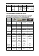
Model
Communication
Interface
SG-UR-I84
SG-UR-I85
SG-UR-I86
RS485
SG-UR-I84-
RS485
SG-UR-I85-RS232
SG-UR-I86-
RS485
POE
SG-UR-I84-
POE
SG-UR-I85-
BT(Bluetooth)
SG-UR-I86-
POE
5. Antenna
The I84/I85/I86 series readers integrate 5dBi, 5dBi and 8dBi right-hand circularly
polarized antennas with voltage standing wave ratio less than 1.3, and support the
expansion of three-way RF channels (Bluetooth version supports extended two
channels) output. It is convenient for enterprise distributed deployment and batch
networking to satisfy different read distance requirements. The following briefly
describes the electromagnetic field distribution of the antenna and the effect of the
field on the tag.
As shown in the figure below, the radiation field of the antenna is divided into three
parts: the main lobe, the side lobe and the back lobe.
Fig 5.1 Antenna radiation field distribution Fig 5.2 3D antenna radiation field distribution
The radiant energy of the antenna is mainly concentrated in the main lobe area. In
practical applications, the tag should be read as far as possible in the main lobe field
of the antenna to achieve a better recognition effect. The upper side lobes have a
higher angle and a longer influence distance, which easily causes cross-region
interference. That is, if adjacent tags are too close, the antenna will read other tags.
Between the main lobe and the lower side lobes, there is a lower zero trap, which will
cause a signal dead zone at this position. The "lower zero depth" vacancy can be filled
by means of beam shaping.
It is also worth noting that when the reader is installed down, the amplitudes of the
vertical and horizontal components of the antenna are constant, so the antenna pattern
will be deformed. At this time, the tag antenna and the reader antenna are not flush,
the read/write range is affected to some extent.