
User Manual


UHF Integrated RFID Reader Manual
Guangdong Sygole Intelligent Technology Co.,Ltd
20
and output functions of the binary signal to the upper monitor. The upper monitor can
use the GPO port to control external devices such as solenoid valves and warning
lights. At the same time, the upper monitor can also capture the signals of devices
such as light sensors and buttons through the GPI port. The GPIO interface will be
routed through the GPIO patch cable and then connected to various GPIO ports.
Fig 4.6.1 GPIO Circuit
The electrical parameters related to GPIO are as follows:
Tab 4.6.1 GPIO electrical parameters
IO external supply
voltage
24V +/-15%
GPO current
≤200mA/ each way, the voltage is determined by external power supply
GPI current
≤10mA/each way, Voltage 14V~30V
The GPIO is derived from an 8-core aerospace connector (male), which is defined as
follows:
Tab 4.6.2 IO interface (M12 Acoding 8pin male) pin definition
No.
Definition
Precast Cable
Color
Schematic Diagram (M12
Acoding 8pin male)
1
24V
Brown
2
NC
White
3
0V
Blue
V 4
IO_1
Pink
5
IO_2
Gray
6
IO_3
Yellow
7
IO_4
Green
8
NC
Red
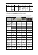
4.7 Ordering Information
Tab 4.7.1 I84/I85/I86 Series Reader Ordering Model Information