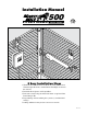
Installation Manual ® E-Z GATE OPENER ® E-Z GATE OPENER 500 UL325 SERIES C LI STED US 500 1-800-543-GATE (4283) • www.mightymule.com ! WARNING MOVING GATE Can Cause Injury or Death SINGLE GATE SYSTEM !W AR NI NG Mo 1. vin g InjuGate ry Can Or De Cau ath se KEE PC LEA Do R! playnot al Gate may in low 3. ga ch Th te ildre mov is area n e at mus gate to an op t us is fo . erat y tim e a r ve e ga e. sepa hicl te rate es on or en ly. tran Pede ce. st rian s 2. 5 Easy Installation Steps 1.
Warning! This equipment is similar to other gate or door equipment and meets or exceeds Underwriters Laboratory Standard 325 (UL 325). However, gate equipment has hazards associated with its use and therefore by installing this product the installer and user accept full responsibility for following and noting the installation and safety instructions. Failure to follow installation and safety instructions can result in hazards developing due to improper assembly.
Table of Contents PLEASE READ THIS FIRST________________________________________________________ 1 IMPORTANT SAFETY INFORMATION_____________________________________________ 2 TECHNICAL SPECIFICATIONS____________________________________________________ 9 BEFORE YOU BEGIN____________________________________________________________ Check Direction of Gate Swing_ ___________________________________________________ Check Existing Gate Size and Material_ _____________________________________________ Check for Pro
Please Read This First! Thank you for purchasing a Mighty Mule® E-Z Gate Opener—GTO's "do-it-yourself" automatic gate opener! When correctly installed and properly used, your Mighty Mule® E-Z Gate Opener will give you many years of reliable service. Please read the following information and watch the enclosed video to ensure you have the correct system for your particular needs. Furthermore, this manual and the DVD will enable you to properly install your Mighty Mule® E-Z Gate Opener.
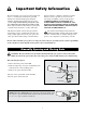
Important Safety Information Because automatic gate openers produce high levels of force, consumers need to know the potential hazards associated with improperly designed, installed, and maintained automated gate opener systems. Keep in mind that the gate opener is just one component of the total gate operating system. Each component must work in unison to provide the consumer with convenience, security, and safety. manual cannot be completely exhaustive in nature.
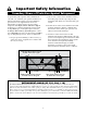
Important Safety Information For the Consumer WARNING: To reduce the risk of injury or death: 1. READ AND FOLLOW ALL INSTRUCTIONS. Failure to meet the requirements set forth in the instruction manual could cause severe injury and/or death, for which the manufacturer cannot be held responsible. 2. Make sure the gate has been properly installed and swings freely in both directions. Repair or replace all worn or damaged gate hardware prior to installation.
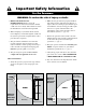
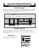
Important Safety Information For the Consumer Entrapment Zones for a proper Pull-To-Open installation: Zone 1 – leading edge of the gate and the fence post. Zone 2 – between the gate and the gate post. Zone 3 – the path of the gate. Zone 4 – the space between the gate in the open position and any object such as a wall, fence, tree, etc. Zone 5 – pinch points between the opener and gate. II. During Installation 4.
Important Safety Information For the Consumer III. After Installation 8. To operate this equipment safely, YOU must know how to disconnect the operator for manual gate operation (see page 2). If you have read the instructions and still do not understand how to disconnect the operator, contact the GTO Service Department. 1. Attach the warning signs (included) to each side of the gate to alert the public of automatic gate operation.
Important Safety Information Secondary Means of Protection Against Entrapment As specified by Gate Operator Safety Standard, UL 325 (30A.1.1), automatic gate operators shall have an inherent entrapment sensing system, and shall have provisions for, or be supplied with, at least one independent secondary means to protect against entrapment. The Mighty Mule® 500 utilizes Type A, an inherent (i.e., built-in) entrapment sensing system as the primary type of entrapment protection.
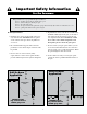
Important Safety Information Required Safety Precautions for Gates Install Warning Signs Warning signs alert people of automatic gate operation and are required when installing the Mighty Mule® 500 Automatic Gate Operator. Furthermore, a walk-through gate must be installed if pedestrian traffic is expected near the vehicular gate. We recommend using the GTO Bulldog Pedestrian Gate Lock (Call the GTO Sales Department at 800-543-4283) for controlled access.
Important Safety Information Required Safety Precautions for Gates ! These warning labels should be found at the locations specified below. If any of them are missing, immediately contact GTO for replacements. C LIS ED T US Product identification and manual operation instruction label (1) installed on right hand side of control box.
Technical Specifications Mighty Mule® 500 E-Z Gate Opener DRIVE CONTROL • Low friction screw drive (linear actuator) rated for -5 ºF to +160 ºF (-20 ºC to +71 ºC). Use of heater bands on arm and control box will enhance performance in extreme cold temperatures. • Powered by a 12 V motor with integral case hardened steel gear reducer. Motor speed reduced to 260 rpm. Generates 680 ft. lb. of torque at 12 V. • Maximum opening arc of 110º.
Before You Begin Check Direction of Gate Swing (Requires Push-To-Open Bracket #FM148—NOT INCLUDED) Your Property Your Property Pull-to-Open Option Instructions begin on page 13 Push-to-Open Option Instructions begin on page 16 Check Existing Gate Size and Material • Gate size: Up to 18 feet or up to 850 lbs—See chart on page 9. • Type of gate material: Vinyl, aluminum, chain link, farm tube, wrought iron, wood (not recommended for solid surface gates).
Before You Begin Column Installation Information IF THIS OPENER WILL BE USED WITH GATES THAT ARE MOUNTED ON MASONRY, BRICK, OR ROCK (etc.) COLUMNS, READ THE FOLLOWING CAREFULLY BEFORE PROCEEDING A. The simplest solution is to install the opener in a push-to-open configuration (requires push-to-open bracket, see accessory catalog).
Before You Begin Tools Needed 3/8” Bit Drill Center Punch Pen 5/16” Bit Pliers Hack Saw Hammer 3/8” wrench Flat Head Screwdriver x2 Level 7/16” wrench Philips Head Screwdriver Adjustable Wrench Clamp Wire Stripper Small Flat Head Tape Measure Items Not Included • Low voltage wire will be needed to run from the transformer to the control box; length depends upon the distance between the transformer power supply and the control box.
Gate Opener Installation Your Property Mounting Pull-to-Open Opener to Gate 1 2 X V M B Q I H X I S R M Y F Q Assemble post bracket parts. Attach opener to gate bracket and secure with required hardware.
Gate Opener Installation Your Property Mounting Pull-to-Open Opener to Gate 6 7 2 U O 1 N Z OPEN gate and re-attach opener with clevis pin. Check for level. Clamp securely. Secure post pivot bracket to post bracket when clearance is OK (Step 5) in both open and closed positions. 9 8 Mark middle of post bracket slots on fence post. Mark middle of gate bracket slots on gate cross support. Remove clamps, post, gate brackets, and opener. Then use a hammer and center punch to mark hole positions.
Gate Opener Installation Your Property Mounting Pull-to-Open Opener to Gate 12 13 R Y 1 S T 2 1 2 Attach gate bracket assembly to gate cross support. Attach and secure opener assembly to brackets. 14 15 Check for level. Adjust post bracket if necessary. Remove bolt excess length on post and gate bracket with hacksaw. Skip This is the end of the Pull-To-Open Hardware Installation. the Push-To-Open Hardware Installation on the next page and to page 19 to finish the gate opener installation.
Gate Opener Installation Your Property Mounting Push-to-Open Opener to Gate 2 1 I V X M PTO Bracket FM148 B Q 11” X I S M Q R F Y Attach opener to gate bracket and secure with hardware required. Assemble post bracket parts. NOTE: A Push-to-Open Bracket FM148 is required for this type of installation (not included).
Push-to-Open Installation Your Property Mounting Push-to-Open Opener to Gate 7 6 U 1 O N Z Secure post pivot bracket to post bracket when clearance is OK (Step 5) in both open and closed positions. CLOSE gate and re-attach opener with clevis pin. Check for level. Clamp securely. 8 9 Remove clamps, post, gate brackets, and opener. Then use a hammer and center punch to mark hole positions. Mark middle of post bracket slots on fence post. Mark middle of gate bracket slots on gate cross support.
Push-to-Open Installation Your Property Mounting Push-to-Open Opener to Gate 13 12 R Y S T Attach gate bracket assembly to gate cross support. Attach and secure opener assembly to brackets. 14 15 Check for level. Adjust post bracket if necessary. Remove bolt excess length on post and gate bracket with hacksaw.
Control Box Installation Control Box Installation 2 1 4’ x. a M A 3’ n. i M Remove control box cover. 3’ n. i M Locate control box mounting area. IMPORTANT: Be sure to mount box at least 3ft from AC power and 3ft off the ground. 3 4 RB 500 12 lt Vo / 7.0 Am pM ou nt G W ck Bla W OR S Red Mount control box to post or fence using screws. 5 G NE PO Position battery in control box as shown. Connect battery leads from control board to battery.
Control Box Installation Control Box Installation RELAY OUT SWITCH BRN ORG SLAVE INPUTS GRN WHT BLUE GRN WHT BLUE 8 NO 7 RED MASTER INPUTS BLK SWITCH BRN ORG BRN ORG MASTER INPUTS GRN WHT BLUE RED GRN WHT BLUE BLK RED COM COM MASTER INPUTS BLK CYCLE CLOSE SAFETY EXIT/ OPEN BRN ORG SHADOW LOOP OPEN EDGE ON Wrong IN MAX BLK SAFETY Insert 7 wires into corresponding color terminals.
Control Box Installation Transformer Wiring Installation 11 12 3 C 1 1 2 Use PVC conduit from ground up to control box. Cut excess cable/strip 1/2” off 2 wires/twist ends. Attach wires to transformer screw terminals. 13 14 ~ ~ 18VAC – + SOLAR RELAY OUT NC RLY-COM NO BRN ORG – + SOLAR SLAVE INPUTS GRN WHT BLUE ~ ~ 18VAC 10” RED BLK SWITCH GRN BRN MASTER INPUTS WHT BLUE ORG RELAY OUT NC RLY-COM NO RED BLK COM Insert one wire into each 18VAC terminal. Colors do not matter.
Control Box Installation Receiver Installation 1 FCC Regulation This device complies with FCC rules Part 15. Operation is subject to the following conditions: 1. This device may not cause harmful interference. 2. This device must accept an interference that may cause undesired operation. ’ 10 x Ma Transmitter distance may vary due to circumstances beyond our control. NOTE: The manufacturer is not responsible for any radio or TV interference caused by unauthorized modifications to this equipment.
Solar Panel Installation (Optional) The table and map illustrate the maximum number of gate cycles to expect per day in a particular area when using from 5 to 30 watts of solar charging power. (see accessory pages in back of this book). The figures shown are for winter (minimum sunlight) and do not account for the use of any accessory items. Accessories connected to your system will draw additional power from the battery.
Solar Panel Installation 3 4 2 ~ ~ 18VAC – + SOLAR RELAY OUT BRN ORG SLAVE INPUTS GRN WHT BLUE RED – + SOLAR BLK 1 NC RLY-COM NO ~ ~ 18VAC 10” BRN MASTER INPUTS WHT BLUE ORG RED BLK Insert RED wire into SOLAR (+) positive terminal and BLACK wire into SOLAR (-) negative terminal. 5 ~ 18VAC ~ – SOLAR + RELAY OUT NC RLY-COM NO GRN Correct Wrong Wrong BRN SLAVE INPUTS WHT BLUE Secure with terminal screws.
Control Box Settings DIP Switches IMPORTANT: Before making any changes to dip switches turn control box off! DIP#1 ON*___soft start enabled OFF___soft start disabled DIP#2 ON*___buzzer warning enabled OFF___buzzer warning disabled (for open and close only) DIP 1 2 3 4 5 6 7 ON 1 2 3 4 5 6 7 DIP#3 ON*___auto-close enabled OFF*__auto-close disabled DIP#4 ON*___push-to-open operation OFF*__pull-to-open operation DIP#5 ON*___D1 mode, constant pressure to operate gate OFF*__B2 mode, momentary contact to ope
Control Box Settings Setting Pull-to-Open (Closed) Gate Limit (for push-to-open go to pg. 27) 2 2 1 3 1 ON Press button on opener remote; gate should start closing. Press button on opener remote again when gate is in desired CLOSED position. With gate in OPEN position, turn control box power ON. 3 4 2 STATUS SET LIMIT ON DIP 1 1 2 3 4 5 6 7 Press and hold the “SET LIMIT” button for 5 seconds. Press button on opener remote to fully open gate.
Control Box Settings Setting Push-to-Open (Open) Gate Limit 2 ~ ~ 18VAC 1 (for pull-to-open go to pg. 26) – + SOLAR RELAY OUT 15A FUSE SLAVE INPUTS MASTERINPUTS 3 2 ON DIP 1 2 3 4 5 6 7 STALL FORCE RECEIVER ON 1 With gate in CLOSED position, turn control box power switch to ON. 3 Press button on opener remote; gate should start opening. Press button on opener remote again when gate is in desired OPEN position.
Control Box Settings Setting Obstruction Stall Force 1 IMPORTANT: For safety reasons the obstructions setting or Stall Force on the Mighty Mule® control board comes from the factory set at MIN (minimum). In many installations this setting will need to be adjusted to overcome the weight and size of the gates.
Control Box Settings Setting Personal Transmitter Code 3 4 STATUS SET LIMIT ON DIP 1 2 3 4 5 6 7 LEARN TRANSMITTER Go to control box. Press and hold the remote and “LEARN TRANSMITTER” buttons simultaneously for 5 seconds. Replace and secure back cover of the opener remote. 5 6 SET LIMIT ON DIP 1 2 3 4 5 6 7 2 LEARN TRANSMITTER 1 Replace control box cover. Release the “LEARN TRANSMITTER” button. Then release the remote button. The new code is now programmed.
Connecting Additional Devices Before You Begin Although GTO strongly recommends the use of additional safety devices, we do not endorse any specific brand names. Only use products that are certified and listed to be in compliance with any applicable UL safety standards (Underwriters Laboratories) and national and regional safety codes.
RG UTS BLK Input Connections RED Connecting Additional Devices GRN BRN MASTER INPUTS WHT BLUE NOTE: • All control inputs are dry-contact, normally open, inputs. DO NOT apply external voltage sources to these inputs. • All inputs are connected with respect to COMMON terminal. • The status light will blink once when its corresponding input is activated. ORG 1 COM: Circuit common (reference for all logic input) • Two (2) terminals to provide extra common connection point.
Connecting Additional Devices BLK COM COM 6 7 OPEN EDGE RED 5 CLOSE EDGE ORG 4 SHADOW LOOP BRN MASTER INPUTS 3 EXIT/ OPEN WHT BLUE 2 SAFETY GRN 1 CYCLE CLOSE Connecting Accessories GRN BLK RED RECEIVER 6 7 3 4 5 According to Application 1 ON DIP NO COM NC V+ V– LOOP LOOP 1 2 3 4 5 6 7 8 9 10 1 According to Application Edge Sensor GTO Loop Detector LOOP 3 1 GTO Photo Beams 1 2 Mighty Mule Push Button Control 1 4 Mighty Mule Vehicle Sensor 1 4 2 ABC 5 GHI JKL 7 P
Maintenance & Troubleshooting Maintenance Tips • Clean the push-pull tube with a soft, dry cloth and apply silicone spray to it at least once per month. • On all gates weighing 250 lb. or more, routinely grease the ball bearing hinges at least 4 times a year; more frequently if the gates are near a coastal area. • While oxidation is a normal part of weathering of equipment that is exposed to the elements, we recommend you apply silicone spray to the front and rear mounts to minimize this effect.
Troubleshooting Guide Symptom Diagnosis One Short Beep Power Problem • • • Fuse Battery Under Load Battery Connections 3 sec tone, 1 sec silence, 3 sec tone Limit Switch Error • • • Master Input Connections Power Cable ORG & GRN, BRN & GRN Terminal Voltages (5VDC) on each. Constant Tone Switch power off and on. If alarm clears, it is an obstruction alarm. If alarm does not clear, then it is a low battery.
S y mp t o m Di a gno si s New installation that will not work. Power Problem • • • Turn Power ON Fuse Battery Connections Dip Switch Settings • Turn #5 dip switch OFF Transmitter • Program the transmitter Antenna Receiver • • Replace transmitter battery Check Antenna Receiver Connections Open or Closed position limit is not programmed. • Reset Limits Gate Bracket is out of adjustment • Adjust Gate Bracket with arm fully retracted.
Repair Service If your Mighty Mule® Gate Opener is not operating properly, please follow the steps below: 1. First use the procedures found in the Maintenance & Troubleshooting Guide (see page 35). 2. If you are unable to solve the problem, call the GTO Service Department at (800) 543-1236, or (850) 575-4144. Refer to the serial number (located on the right hand side of the control box) and date of purchase when calling for assistance. 3.
Conversion Chart Converting Metric Units to English Equivalents When You Know Multiply By To Find Symbol centimeters meters kilograms 0.3937 3.2808 2.2046 inches feet pounds in. (or ") ft. (or ') lb. (or #) Converting English Units to Metric Equivalents When You Know Multiply By To Find Symbol inches feet pounds 2.5400 0.3048 0.4535 centimeters meters kilograms cm m kg Converting Temperature deg. Celsius deg. Fahrenheit (ºC x 1.8) + 32 deg. Fahrenheit (ºF-32) ÷ 1.8 deg.
® E-Z GATE OPENERS ACCESSORIES Accessories are Available From Your Retail Store Solar Panel (FM121) The Solar Panel is a 5 watt solar powered battery charger for use with the FM500 & FM502 gate operator systems. Particularly suited for remote installations, each Solar Panel comes with tubular steel support, mounting clips, wire connectors, and 8 ft. of low voltage wire (see Low Voltage Wire for additional wire).
Accessories are Available From Your Retail Store (con't) Wireless Entry Intercom / Keypad (FM136) Allows owner to screen guest at the gate before allowing access to the property. Keypad also allows owner to give up to 25 programmable entry codes to family, friends or approved delivery personnel. Codes can be permanent of temporary. Can be wireless up to 500 feet or hard wired up to 1000 feet. Additional base stations available (F3101MBC). Replacement Battery (FM150) Standard 12 volt, 7.
® E-Z GATE OPENERS For sales call toll free: 1-800-543-GATE (4283) The GTO, Inc. Sales Department is open Monday – Friday 8:00 A.M. – 5:00 P.M. (Eastern Time) For technical service Call toll free: 1-800-543-1236 The GTO, Inc. Technical Service Department is open Monday – Friday 8:00 A.M. – 7:00 P.M.