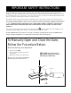
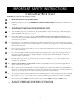
¨ + LIS TED 75 SERIES AUTOMATIC GATE OPERATOR FOR VEHICULAR SWING GATES FOR INSTALLATION MANUAL THE PROFESSIONAL INSTALLER Receiver Control Box with Battery Post Bracket Assembly 120 Volt Indoor Transformer (surge protector not supplied) Run 1000' (max.) of low voltage wire to control box from transformer. (wire not included) Warning Sign Gate Bracket GTO/PRO 2000 Power Cable Closed Position Positive Stop Plate PVC conduit (not included) to protect wire from lawn mowers and weed eaters.
GTO/PRO 2000 series automatic gate operators are intended for use with vehicular swing gates. These operators can be used in Class I, Class II and Class III applications. VEHICULAR GATE OPERATOR CLASS CATEGORIES Residential Vehicular Gate Operator-Class I: A vehicular gate operator (or system) intended for use in a home of one-to-four single family dwelling, or a garage or parking area associated therewith.
Table of Contents Gate Operator Class Categories ----------------------------------------- inside front cover Units and Standards Conversion Chart --------------------------------- inside front cover IMPORTANT SAFETY INSTRUCTIONS ------------------------------------- page 1 Warning Signs and Labels ---------------------------------------------------------- page 7 Technical Specifications ------------------------------------------------------------- page 8 Single Gate Operator Parts List --------------------
IMPORTANT SAFETY INSTRUCTIONS Because automatic gate operators produce high levels of force, all system designers, installers, and consumers have an obligation to know the potential hazards associated with improperly designed, installed, or maintained gate operator systems. Keep in mind that the gate operator is just one component of the total gate operating system. Each component must work in unison to provide the consumer with convenience, security, and safety.
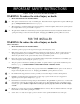
IMPORTANT SAFETY INSTRUCTIONS FOR THE SYSTEM DESIGNER WARNING: To reduce the risk of injury or death: 1. READ AND FOLLOW ALL INSTRUCTIONS. 2. This operator is intended for use only on vehicular gates. Pedestrians must be supplied with a separate walk-through gate (see Entrapment Protection illustration on page 6). 3. When designing a system that will be entered from a highway or main thoroughfare, make sure the system is placed far enough from the road to prevent traffic congestion. 4.
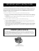
IMPORTANT SAFETY INSTRUCTIONS III. After Installation 1. Review ALL safety instructions with the consumer/end user. Explain the basic operation and safety systems of the entire gate operator system, including disconnecting the operator for manual operation of the gate. 2. 3. Attach the warning signs (included) to each side of the gate to alert public of automatic gate operation. Take a photo of warning signs installed on gate. Record the date of the photo for your reference. SAVE THESE INSTRUCTIONS.
IMPORTANT SAFETY INSTRUCTIONS Secondary Means of Protection Against Entrapment As specified by Underwriters Laboratories Inc. UL 325 (30A.1.1), automatic gate operators shall have provisions for, or be supplied with, at least one independent primary and one independent secondary means to protect against entrapment. GTO gate operators utilize Type A, an inherent entrapment sensing system, as the primary type of entrapment protection.
IMPORTANT SAFETY INSTRUCTIONS Consumer/End User WARNING: To reduce the risk of injury or death: 1. READ AND FOLLOW ALL INSTRUCTIONS. 2. Distribute and discuss copies of the IMPORTANT SAFETY INSTRUCTIONS with all persons authorized to use your gate. 3. Always keep people and objects away from the gate and its area of travel. NO ONE SHOULD CROSS THE PATH OF THE MOVING GATE. 4. Your automatic gate is not for pedestrian use.
IMPORTANT SAFETY INSTRUCTIONS Required Safety Precautions for Swing Gates Install Warning Signs Warning signs alert people of automatic gate operation and are required when installing the GTO/PRO 2000 series gate operator. Furthermore, a walk-through gate must be installed if pedestrian traffic is expected near the vehicle gate. We recommend the GTO Bulldog Pedestrian Gate Lock (see Accessory Catalog) for controlled access.
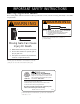
IMPORTANT SAFETY INSTRUCTIONS Warning Signs and Labels These warning labels should be found at the locations specified below. If any of them are missing, immediately contact GTO for replacements. WARNING ! ! WARNING MOVING GATE Can Cause Injury or Death 1. 2. 3. KEEP CLEAR! Gate may move at any time. Do not allow children to operate gate or play in gate area. This gate is for vehicles only. Pedestrians must use separate entrance.
Technical Specifications GTO/PRO 2000 Series Swing Gate Operators DRIVE • • • • • • • • • • • • • • • • • • • • • Low friction screw drive (linear actuator). Temperature rating of motor -30 ºF (-34 ºC) to +160 ºF (71ºC). Powered by a 12 Vdc motor; generates 650 ft. lb. of torque at 12 V. 110o degree opening time approximately 15 to 20 s. Maximum push-pull tube stroke 24”. Operator length with push-pull tube fully retracted is 39” (99 cm), mounting point to mounting point. Limit switches are internal.
Installation of First (Single) Gate Operator Single Gate Operator Parts List Parts Gate Operator with 6 ft.
Single Gate Operator Parts List Control Box and Electrical Components ! WARNING Moving Gate Can Cause Injury Or Death 1. KEEP CLEAR! Gate may move at any time. 2. Do not allow children to operate gate or play in gate area. 3. This gate is for vehicles only. Pedestrians must use a separate entrance. RB3270 OTHER MATERIALS YOU MAY NEED BEFORE YOU START THE INSTALLATION: Depending on the type of gate and fence post, you may need some additional materials/hardware.
Single Gate Operator Installation Pull-to-Open Single Gate (gate opens into the property) The diagram below is an example of a single leaf, pull-to-open installation on an ornamental iron gate. If you are installing a Push-to-Open (gate opens out from the property) system, see page 31. Or, if you are mounting the operator on a masonry column, please refer to page 36 before proceeding.
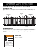
Installing The Post Bracket Assembly The position of the post bracket determines the leverage of the operator and the clearance between the operator and the gate. 8” Wood Post 6” Wood or Metal Post The post bracket is designed to work on a flat fence post. Fence posts must be at least 6” square in order to mount the post bracket. NOTE: The best method of attaching the post bracket to metal post is welding.
Step 4: Position the post bracket on the fence post with the mounting holes centered over the scribe line. The post bracket should be flush with the edge of the fence post closest to the gate (see illustration). Mark the position of post bracket holes on the fence post. Step 5: Drill holes in fence post as marked using a 1/2" drill bit. Install the post bracket using the 1/2" x 10" carriage bolts, 1/2" washers, and lock nuts (provided).
Connecting Operator to Post Bracket Assembly Step 7: Tap the rear mount onto the back of the operator. Align the 3/ " hole in the rear mount with 3/ " hole in the back of the 8 8 operator and insert the 3/8" bolt through the holes and secure it with the lock nut. Rear Mount Step 8: Position rear mount between post pivot brackets. Place 1/2" washers between rear mount and post pivot brackets. Align 1/2" hole in rear mount and washers with holes in post pivot brackets.
Step 10: Open the gate to the desired position (at least 10º and no greater than 110º). Position the operator so that the gate bracket just rests against the gate. Check the clearance between the operator and the gate. The operator should only make contact with the gate at the gate bracket. However, there should not be too much clearance between the operator and the gate, or the operator will fully extend before it reaches the closed position. See illustration at right for examples of clearance.
Installing the Open and Closed Position Stops The positive stops hold the gate firmly in the open and closed positions. The positive stops also form the boundaries of the gate operating arc and help stabilize the gate. Moreover, a stable gate helps to maintain the long life of your automatic gate opener system. To further enhance the stability and security of your gate, install the optional GTO Automatic Gate Lock (see Accessory Catalog).
Step 15: Hinge point Close the gate. Position the closed position stop plate on the end of the gate frame at mid-height. Extend the stop plate to make contact with the fence post at that position. Closed Position Stop Plate Install the closed position stop plate using appropriate hardware for the type of gate (U-bolts for tube or chain link gate, wood or lag screws for wood gates, etc.). This hardware is not provided. The gate must open no more than 110° Reattach the operator to the gate bracket.
Step 17 Make sure the control box power switch is in the OFF position. Unscrew and remove the control box cover and slide the battery into position with its terminals to the left (see illustration). Push battery down until it fits snugly in control box. Connect the BLACK battery wire to the NEGATIVE (–) battery terminal. Connect the RED battery wire to the POSITIVE (+) terminal. Pay close attention to the color of the wires. If the wires are connected incorrectly, the control board will be damaged.
Powering the System • The transformer is intended for indoor use. If the transformer can only be plugged into an outside electrical outlet, a weatherproof housing or cover (available at electrical supply stores) must be used. • Solar power options are available; see Solar Chart on next page. • All low voltage wire used for powering the GTO/PRO gate operators MUST be 16 gauge (minimum) dual conductor, multi-stranded, direct burial wire.
Solar Zones and Gate Activity ;;;;; ;;;;; ;;;;; ;;;;; ;;;;; This table and map illustrates the maximum number of cycles per day to be expected in a particular area, using GTO’s 10 watt solar panels (see Accessory Catalog). Figures are shown for winter (minimum sunlight) and do not account for use of any accessory items. Accessories will draw additional power from the battery.
POWER IN RE OPN EDG CLS EDG GRN BLU ORG BLK RED 18VAC SOLAR ~ ~ – + FIRST OPERATOR SECOND OPER Step 24: RED BLACK Strip 3/16” off the ends of the low voltage wire and twist each wire end tightly. Attach these ends to the 18VAC terminals located on the POWER IN terminal block (see illustration above). Make sure the exposed wires DO NOT touch each other! Insert one transformer wire in an 18VAC terminal. Insert the other transformer wire into the remaining 18VAC terminal.
CONTROL BOARD SETTINGS DIP Switches The four DIP switches on the control board match the operator with the type of gate on which it is installed. For example, gates may pull-to-open or push-to-open. Prior to packaging, the GTO/PRO 2000 series control board was configured for single swing gates that pull-to-open (open into the property). If your gate type matches this configuration, you DO NOT need to adjust the DIP switches; Proceed to the Potentiometers section on the next page.
Potentiometers The three (3) potentiometers on the control board operate like a volume control on a radio. They control the auto close timer, inertia, and obstruction sensitivity of the operator. Use a small slotted screwdriver to turn the arrow in the center of the potentiometer. Clockwise rotation increases the setting (MAX). Counterclockwise rotation decreases the setting (MIN). AUTOCLOSE 60 OFF 120 INERTIA MIN MAX MAX 2 3 MIN 1 ON PULL/PUSH SNGL/DUAL SEQ1 SEQ2 4 OBSTRUCT SENS.
Setting the Personal Transmitter Code All GTO transmitters are set to a standard code at the factory and are ready to activate your automatic gate operator. For your safety and security, however, we strongly recommend that you replace the factory setting with your own personal code. Follow the directions below: 1. Remove the Transmitter Cover Grasp the sides of the access cover and slide it away from the transmitter button (see illustration).
3. “Teach” the New Code to Control Board Memory E. OFF 120 INERTIA STATUS LED MIN MAX 3 MIN MAX 2 PULL/PUSH SNGL/DUAL SEQ1 SEQ2 4 OBSTRUCT SENS. 1 D. Turn control box power switch OFF. Unscrew and remove the control box cover. Press and hold the LEARN button on the control board, and turn the power switch ON. Release LEARN button. Wait 15 seconds for the receiver to charge. Press and hold transmitter button until the red STATUS LED comes ON. Release transmitter button.
Setting the Closed Position Limit Switch Step 29: Remove the rear cover of the operator to gain access to the limit switches and the limit switch cams. IMPORTANT: The inner switch cam assembly is factory set. Do not attempt to adjust the inner switch cam. This switch cam is not adjustable; attempting to move it will cause damage to the operator! Step 30: For Pull-to-Open Installations: The open position of the gate was determined when you installed the GTO/PRO 2000 on the open gate (page 15, Step 12).
Step 31: Secure all bolts, nuts, and washers on the post bracket and gate bracket assemblies. Cut off the ends of the bolts extending beyond the tightened nuts. Step 32: Install warning signs on both sides of the gate (see page 7) using nylon cable ties (provided) or screws.
Connecting Additional Safety Devices The GTO/PRO 2000 series operators are equipped with built-in obstruction sensitivity. These operators are designed to stop and reverse the gate for 2 seconds when it comes in contact with an obstruction. However, obstruction sensitivity, even when properly adjusted, may not be sensitive enough to prevent bodily injury in some circumstances. To augment protection against entrapment, GTO suggests using safety edge sensors or photoelectric sensors.
Compatible Safety Devices Although GTO strongly recommends the use of safety devices, we do not endorse any specific brand names. Below is a list of some products compatable with GTO operators systems, some of which require their own power supply. Check with the individual manufacturer for specific power needs. Only use products that are certified and listed to be in compliance with national and regional safety codes. Safety Edges Miller Edge, Inc.
Connecting Accessories Make sure the control box power switch is OFF before connecting accessories. The ACCESSORY terminal block is the connection point for accessories such as push buttons, safety loops, intercoms, etc. The ACCESSORY terminal marked GRN (green) is the common ground for all accessories. GRN is paired with the terminals shown below when connecting accessories to the control board. WHT (white) used with GRN (green): Functions as a normally open contact.
Push-to-Open Installation Determining The Mounting Position of The Post Bracket Assembly Swinging gates shall not open into public access areas! Review IMPORTANT SAFETY INSTRUCTIONS A "Push-to-Open" gate opens out from the property. The operator is installed on this type of gate while in the closed (not open) position. Because every gate installation varies, the push-to-open installation of the GTO/PRO 2000 and GTO/PRO 2200 will need to be customized.
Step PTO-3: With the gate in the closed position, connect operator to gate bracket assembly as in Step 12 on page 15 and clamp into position. Mark the point where the gate bracket will be attached to the gate. Drill the holes and mount the gate bracket. Reattach gate bracket to arm with clevis pin and hairpin clip. Step PTO-4: Now go back and follow the instructions for the rest of the installation from Installing the Open and Closed Position Stops (see step 13-15).
Maintenance and Troubleshooting Guide Maintenance: • On all gates weighing 250 lb. or more, routinely grease the ball bearing hinges at least 4 times a year; more frequently if the gates are near a coastal area. • A few mothballs in the control box helps to keep out insects which can damage circuits. • Apply silicone spray to the push-pull tube at least once per month.
The transformer: Two things can cause failure. The first is shorting the leads during the installation, or letting the strands touch at the terminal on the control board. The second is a static charge (generally associated with a lightning storm or power outage); use of a surge protector will help protect the transformer against static charges. Testing the battery: This is a 12 V, 7 Ah battery. The proper way to test the battery is to perform a load test.
Warranty and Repair Service If the GTO gate operator system is not operating properly, please follow the steps below: 1. First, check the Maintenance and Troubleshooting Guide (see page 33). 2. Call your dealer or installer for assistance. 3. If your dealer or installer is unable to resolve the problem, call the GTO Service Department at (850) 575-0176 to discuss the problem with a service technician.
Column Installation Information 12" MAX The GTO/PRO 2000 and GTO/PRO 2200 can be mounted on any size column, but the gate hinge cannot be more than 12” from the mounting surface of the post bracket. The edge of the post bracket must be aligned with the edge of the column face where the hinges are mounted. If these conditions cannot be met, and you do not want to pocket the column, call GTO’s Service Department for alternative solutions..
GTO/PRO 2200 Dual Gate System Second Unit Parts List Parts Gate Operator with 50’ Power Cable Gate Bracket Post Bracket Post Pivot Brackets (2) Rear Mount Closed Position Stop Plate Hardware (not to scale) 2" x 10" Carriage Bolt (2) 1/ 2" x 33/4" Bolt (2) 1/ 2" x 23/4" Bolt (3) 3/ 8" 1/ 2" 11/4"dia x 1/2" Nylon Spacer (2) 1/ 2" Receiver Mounting Screw (4) 8" Nylon Cable Tie (14) 1/ x 11/2" Bolt (1) x 11/4" Clevis Pin (1) Hairpin Clip (1) 37 x 17/16" Metal Spacer (1) 2"dia 1/ 2"
Installing The Second Unit The diagram below shows a dual gate, pull-to-open (gate opens into the property) installation on iron gates. If you are installing a Push-to-Open (gate opens out) system see Push-to-Open Installation starting on page 31. Receiver Control Box with Battery Post Bracket Assembly 120 Volt Indoor Transformer Gate Bracket GTO/PRO 2000 – First Operator (Surge Protector, not supplied) Power Cable Run up to 1000' of low voltage wire to control box from transformer.
StepD3: Return to page 11, Single Gate Operator Installation, and repeat Step 1 through 15 to install the second operator. This time in Step 15, however, the closed position stop plate on the first gate will contact the leading edge of the second gate. Connecting the Second Operator to the Control Board Step D-4: Turn power switch OFF. Remove the control box cover. Using a steel punch or screwdriver, remove the thin plastic knockout in the second operator connector hole at the bottom of the control box.
Step D-7: Cut slot into driveway and lay the 25 foot power cable for the second operator in this slot (see Illustration on page 38). NOTE: DO NOT attempt to splice the power cable, and DO NOT remove the connector from the end of the cable. If you need a longer cable, 35 foot and 40 foot power cables are available (see Accessory Catalog). Setting the Control Board for Dual Gate Installations DIP Switches The Control Board DIP switches must be set to accommodate your particular type of installation.
OBSTRUCT SENS. PULL/PUSH SNGL/DUAL SEQ1 SEQ2 SEQ2 = ON If SEQ1 is set to OFF, and SEQ2 is set to ON, the FIRST OPERATOR will open first, and the SECOND OPERATOR will close first (see illustration). 1 2 3 4 SEQ1 = OFF ON FIRST OPERATOR OPENS FIRST, SECOND OPERATOR CLOSES FIRST PULL/PUSH SNGL/DUAL SEQ1 SEQ2 1 2 3 4 SEQ2 = ON ON OBSTRUCT SENS. If SEQ1 is set to ON, and SEQ2 is set to ON, The FIRST OPERATOR opens and closes first. MIN MAX LEARN OBSTRUCT SENS.
Accessories Available Through Your Dealer GTO Digital Keypad (F300) 1 2 3 4 5 6 7 8 9 The weatherproof digital keypad can be easily installed as a wired or wireless keypad for all GTO swing and slide gate operators, and as a wired keypad for the Bulldog Pedestrian Gate Lock. It can be programmed to recognize fifteen different personal identification number (PIN) codes. Each code is face programmable with additional security features built in. Requires 3 AA batteries (not included).
ACCESS-ories Master® Pin Lock (RB975) Column Mount Lock Receiver (433IH) for GTO/PRO 1000/1200 Master® Pin Lock (FM320) For mounting the Automatic Gate Lock or Bulldog Pedestrian Lock in areas with limited space between the gate and post, such as brick columns or walls. for GTO/PRO 2000/2200 The pin lock is a substitute for the clevis pin at either or both mounting points of the GTO/PRO 1000 operator arms and the gate bracket end of the GTO/PRO 2000.
ACCESS -ories Standard Replacement Transformer (RB570) – Standard 18 Volt, 40 VA, AC transformer for chargingthe battery included with the GTO/PRO 2000 series gate operators. Bulldog Replacement Charger (RB421) – Standard 12 volt DC charger (not shown) for maintaining battery included with the Bulldog Pedestrian Gate Lock. Replacement Batteries RB500 – The standard 12 volt, 7.0 ampere-hour, maintenance-free battery for all GTO/PRO gate operators.
Installation Check list The installation of this operator conforms to CLASS __________. The installer verifies that (each item except safety edges must be checked): ____ Recommended safety edges were installed. ____ Customer was informed that this gate is for vehicular use ONLY. Pedestrians MAY NOT use this gate. ____ A separate gate or entrance was installed for pedestrian use. ____ Closed position stop plate was securely fastened.