INSTALLATION INSTRUCTIONS FOR GTO/PRO SW-5000 and GTO/PRO SW-6000 AC Powered Swing Gate Operators LI US STED WARNING! • READ ALL INSTRUCTIONS COMPLETELY before attempting installation and use; failure to do so may result in serious injury or death! • This unit must only be installed by an experienced technician! • DANGER: HIGH VOLTAGE! Contact with gate operator circuitry can cause serious injury or death! Operator power must be disconnected before servicing! • This gate operator produces a high level o
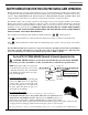
The GTO/PRO SW-5000 and SW-6000 automatic swing gate operators are intended for use with vehicular gates. The operators can be used in Class I, II, III, and IV applications. VEHICULAR GATE OPERATOR CLASS CATEGORIES Residential Vehicular Gate Operator-Class I: A vehicular gate operator (or system) intended for use in a home of one-to-four single family dwelling, or a garage or parking area associated therewith.
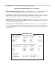
TABLE OF CONTENTS Gate Operator Class Categories ....................................................................................................................Inside Cover Metric Conversion Chart .......................................................................................................................................................Inside Cover Safety Instructions for the GTO/PRO-SW-5000 and GTO/PRO SW-6000 Swing Gate Operators ...................................
Important Safety Instructions SAFETY INSTRUCTIONS FOR THE GTO/PRO SWING GATE OPERATORS Because automatic gate operators produce high levels of force, all system designers, installers, and consumers have an obligation to know the potential hazards associated with improperly designed, installed, or maintained gate operator systems. Keep in mind that the gate operator is just one component of the total gate operating system.
Important Safety Instructions IMPORTANT SAFETY INSTRUCTIONS for the System Designer WARNING: To reduce the risk of injury or death: 1. READ AND FOLLOW ALL INSTRUCTIONS. 2. This operator is intended for use only on vehicular gates. Pedestrians must be supplied with a separate walkthrough gate (see Entrapment Protection illustration on page 6). 3.
Important Safety Instructions III. After Installation 1. Review ALL safety instructions with the consumer/end user and explain the basic operation and safety systems of the entire gate operator system, including operation of the foot pedal release. 2. Inform the consumer/end user that servicing of the operator must only be done by an experienced technician. 3. Attach the warning signs (included) to each side of the gate to alert public of automatic gate operation.
Important Safety Instructions IMPORTANT SAFETY INSTRUCTIONS Specific to Secondary Means of Protection Against Entrapment As specified by Underwriters Laboratories Inc. UL 325 (30A.1.1), automatic gate operators shall have provisions for, or be supplied with, at least one independent primary and one independent secondary means to protect against entrapment. GTO gate operators utilize Type A, an inherent entrapment sensing system, as the primary type of entrapment protection.
Important Safety Instructions IMPORTANT SAFETY INSTRUCTIONS for the Consumer/End User WARNING: To reduce the risk of injury or death: 1. READ AND FOLLOW ALL INSTRUCTIONS. 2. Distribute and discuss copies of the IMPORTANT SAFETY INSTRUCTIONS manual with all persons authorized to use your gate. SAVE THESE INSTRUCTIONS. 3. Always keep people and objects away from the gate and its area of travel. NO ONE SHOULD CROSS THE PATH OF THE MOVING GATE. 4. Your automatic gate is not for pedestrian use.
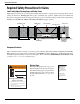
Important Safety Instructions Required Safety Precautions for Gates Install Safety Edges, Warning Signs, and Safety Covers Safety edges provide the gate operator with an integral safety feature by stopping and reversing gate direction upon sensing an obstruction. Warning signs alert people of automatic gate operation. Safety covers prevent hands and fingers from being pinched by the moving parts of the gate operator.
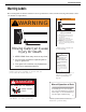
Important Safety Instructions Warning Labels These warning labels should be found at the locations specified below. If any of them are missing, immediately contact your installer for replacements. ! WARNING ! WARNING Moving Gate Can Cause Injury Or Death 1. KEEP CLEAR! Gate may move at any time. 2. Do not allow children to operate gate or play in gate area. 3. This entrance is for vehicles only. Pedestrians must use a separate entrance. 4. Read the owner's manual and safety instructions. 5.
TECHNICAL SPECIFICATIONS for the GTO/PRO SW-5000 & SW-6000 AC Swing Gate Operators Motor •GTO/PRO SW-5000: 1/2 hp GTO-Leeson 1625 rpm TEFC; C-Face connection; 115 V, single phase. •GTO/PRO SW-6000: 1 hp GTO-Leeson 1600 rpm TEFC; C-Face connection; 115 V, single phase. Gear Reducer •Totally enclosed 900:1, double reduction gear reducer, with vertical motor flange. •Machine cut bronze gears run in an oil bath. •Oil temperature range: –22 °F to 806 °F (–30 °C to 430 °C).
PARTS IDENTIFICATION GTO/PRO SW-5000 and GTO/PRO SW-6000 AC Powered Swing Gate Operators Receiver (1) ® AUTOMATIC GATE OPERATORS GTO Transmitter(1) ! WARNING IMPORTANT SAFETY INSTRUCTIONS GTO/PRO SW-5000 & SW-6000 AC Powered Swing Gate Operators Moving Gate Can Cause Injury Or Death Installation Instructions for GTO/PRO SW-5000 & SW-6000 AC Powered Swing Gate Operators WARNING Entry Control Warning Signs (2) Manual Operation of Gate STANDARDS Conforms to UL 325 WARNING LISTED ® 9901178 or clo
Parts Identification ...
INSTALLING THE GATE OPERATOR THIS UNIT MUST ONLY BE INSTALLED BY AN EXPERIENCED TECHNICIAN. Preparation of the Gate Before installing the GTO/PRO swing gate operator, make sure: • the gate is properly installed. • the gate is plumb, level, and moves freely. • the gate does not bind or drag on the ground. Operator Installation Overview The diagram below is an example of a single swing gate installation with required safety features. The operator must be installed on the inside of the gate.
Using the Mounting Template The mounting template (see insert) is designed to simplify mounting the operator. It provides the installer with the proper locations for running power and accessory wiring conduits. The template is also marked with the correct distance between the operator mounting holes and shows the installer how to position the operator for the correct clearance between the housing and the gate. NOTE: The operator must be securely mounted on a level concrete pad.
Square Column Center point of gate hinge Closed Gate Housing Knuckle Cover Pivot point of operator 2 ft. square area IMPORTANT: Pivot point of operator should be no more than 2 ft. from the center point of gate hinge in either direction. Opened Gate Also, be sure the operator housing will not be hit by a fully open gate and that gate column will not interfere when housing is installed. Round Column Center point of gate hinge Closed Gate Housing Knuckle Cover Pivot point of operator 2 ft.
Connecting the Gate Arm Assembly 1. Fit the end of the reducer arm on the end of the upper spline (see illustration at right). Align the bolt holes of the parts and join them with (1) 1/2” bolt. Gate Arm Adjusting Bracket 1/2" x 1-1/2" bolts Upper Spline 1/2" x 1-1/2" bolts 1/2" x 2-1/2" bolt Reducer Arm 1/2" x 2" bolt 2. Fit the ends of the reducer arm, stop bracket and gate arm together (see illustration). Align the bolt holes of the parts and join them with (1) 1/2” bolt and (1) Nyloc nut.
ADJUSTING THE LIMIT SWITCHES The limit switches determine how far the gate travels to open and close. The closer the limit nut is to the limit switch, the less distance the gate will travel to open or close. Adjust the limit switches by moving the limit nuts. MAKE SURE THE OPERATOR POWER IS OFF BEFORE ATTEMPTING TO ADJUST THE LIMIT SWITCHES. Lift and release the limit switch plate to unlock the limit nuts (see illustration at right).
GATE OPERATOR CONTROL BOARD Reset/Learn Button Diagnostic LEDs PWR OK 5 6 TMR. OFF/ON INTERN.ERR. 4 SEQUENCE 2 LIM SW ERR. DIP switches 3 MAX GATE R/L SEQUENC 1 SENSOR ERR. OPEN MTR. MIN MAST/SLV 2 MAX TIME SWNG/SLD 1 OBSTRUCT RST / LEARN ON TIMER ON CLS. SENS. (Not Actual Size) EDGE 6 EDGE 5 EDGE 4 OPN. SENS. EDGE 3 TB1 Potentiometers EDGE 2 EDGE 1 MIN MAX COM COM INERTIA – MIN DUAL GATE INTERFACE MAX RX + – TX CLOSE TIMER TB2 + G 60 GTO RCVR.
CONTROL BOARD SETTINGS THESE SETTINGS SHOULD BE ADJUSTED ONLY BY AN EXPERIENCED INSTALLER OR TECHNICIAN! RST/LEARN: 1) Use to set transmitter code in control board memory. 2) Press this button to clear the diagnostic and error LEDs. DIP switches (To change these settings, you must turn power OFF; move DIP switches ON 1 the switch; then turn power back ON.) ST / LEARN SWNG/SLD (swing or slide gate operation): SWNG = swing gate SLD = slide SWNG/SLD gate [factory default is SWNG].
Error Condition LEDs (Press RST / LEARN to clear these LEDs) SENSOR ERR.: Indicates obstruction sensing circuitry has malfunctioned. LIM SW ERR.: Indicates a fault in the limit switch or limit switch wiring. This LED cannot be reset using the RST/ LEARN button. OPEN MTR.: Control board does not detect the operator motor. INTERN ERR.: Indicates a microprocessor error has occurred. An internal error cannot be reset by pressing the RST/ LEARN button.
SETTING A PERSONAL TRANSMITTER CODE All GTO transmitters are set to a standard code at the factory and are ready to operate the GTO/PRO SW-5000 & GTO/PRO SW-6000 series operators. For safety and security, however, we strongly recommend that the factory setting be replaced with a personal code. Follow the directions below: 1. Remove the Transmitter Cover Grasp the sides of the access cover and slide it away from the transmitter button (see illustration).
INSTALLING SAFETY COVERS ON THE OPERATOR The movement of the gate arm assembly presents the possibility of physical injury to installers, maintenance technicians, and consumers/end users. The installer must know the areas of the operator where a person’s hands and fingers could be pinched. Furthermore, the installer must take reasonable precautions when installing a gate operator to prevent this type of injury (UL 325; 51.8.4 [a], [3]).
COMPATIBLE SAFETY DEVICES Although GTO strongly recommends the use of safety devices, we do not endorse any specific brand names. Below is a list of some products compatable with GTO operators systems, some of which require their own power supply. Check with the individual manufacturer for specific power needs. Only use products that are certified and listed to be in compliance with national and regional safety codes. Check with manufacture to insure product compatibility.
Installing a Dual Slide Gate Operator System IMPORTANT: With a dual gate system certain control board settings and connections are required on the MASTER unit only and some are required on both the MASTER and the SLAVE unit. The list below gives an overview. MASTER • Gate Sequencing (set on MASTER, left OFF on SLAVE) • Alarms (wired to MASTER only) • Entry Devices (all entry/exit devices, shadow loops, Fire Dept.
Dual Gate Interface Master Control Board (MAST) COM Use 22 AWG (minimum) individually shielded paired direct burial wire manufactured by Belden Inc. to connect the two units. GND COM – DUAL GATE INTERFACE RX + – TX TB2 + ONLY BELDEN® type 8723, 22 AWG 2-pair shielded (w/ one ground) wire is compatible with the DUAL GATE INTERFACE TERMINAL. G GTO RCVR. R TB3 B Auxiliary Control Board (SLV) COM GND COM – DUAL GATE INTERFACE RX + – TX TB2 + G GTO RCVR.
24 Use Rigid Conduit for inbound AC. Operator Pivot Cover Knuckle Cover Slave Operator Safety Edge Warning Sign Safety Edge Dual Gate Interface Run Belden Wire® ONLY in its own conduit 22 AWG type 8723 2-pair shielded with GROUND Safety Edge Warning Sign Receiver Operator Use Rigid Conduit for inbound AC.
MAINTENANCE WARNING: ALWAYS TURN OPERATOR OFF BEFORE ADJUSTING OR SERVICING IT. Maintenance Schedule: Test the gate operator, accessories, and safety devices monthly. Service the gate operator, accessories, and safety devices regularly. Maintenance Checklist Test the safety edges (Grasp edges and squeeze). Check the obstruction settings (in both open and close modes). Check for wear on all moving parts, and tighten bolts as necessary. Check the gear box for any sign of oil leakage.
TROUBLE SHOOTING GUIDE WARNING: ALWAYS TURN OPERATOR OFF BEFORE ADJUSTING OR SERVICING IT. 1. If the PWR OK light will not come on: A. Check the operator for inbound power. B. The operator is in “learn” mode (see SETTING A PERSONAL TRANSMITTER CODE on page 19). 2. If the unit does not function: A. Check the operator for inbound power. B. Make sure the ON/OFF switch is in the ON position. C. Control board may be damaged; call the GTO Service Department. 3.
WARRANTY AND REPAIR SERVICE If the GTO gate operator system is not working properly, please follow the steps below: Instructions for the Consumer/End User: 1. Call your dealer or installer for service. Only an experienced technician may service this unit. 2. If your dealer or installer is unable to solve the problem, they will contact the GTO Service Department. Instructions for the Dealer/Installer: 1. Call the GTO Service Department at (850) 575-0176 to discuss the problem with a service technician. 2.
INSTALLATION CHECK LIST The installation of this operator conforms to CLASS __________. The installer verifies that (each item must be checked): ___ Required safety edges were installed. ___ Required pivot cover and knuckle cover were installed. ___ The knuckle cover warning decals (2) were affixed to the knuckle cover. ___ Customer was informed that this gate is for vehicular use ONLY. Pedestrians MAY NOT use this gate. ___ A separate gate or entrance was installed for pedestrian use.