
User Guide

23
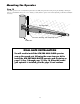
Step 3
Lay the measured length of low voltage wire in a trench following a path from
the selected electrical outlet to the control box. Wires coming up from the
ground should be run through PVC conduit to protect them from lawn mower
blades, weed eaters, and grazing animals. Be sure to bury the wire laid in the
trench.
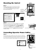
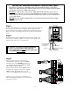
Step 4
Feed the low voltage wires upward through the strain relief opening on the
lower left of the control box. Pull 6" to 8" of wire into the control box and
tighten the strain relief screw to secure the wires.
IMPORTANT INFORMATION ABOUT LOW VOLTAGE WIRE
The only wire acceptable for use with GTO products is 16 gauge multi-stranded, low voltage, PVC
sheathed wire. This particular gauge enables the transformer to provide an adequate charge through the
control board to the battery at distances up to 1000 ft.
DO NOT use telephone wire or solid core wire. Unlike multi-stranded wire, these types of wire are
inadequate for use with your gate operator system. Telephone wire and solid core wire do not deliver
enough voltage for your gate operator to function and will cause the system to go into a condition known
as "low voltage lockout."
NEVER splice wires together. Splicing permits corrosion and seriously degrades the wire's ability to
carry an adequate current.
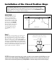
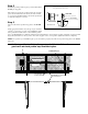
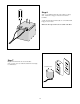
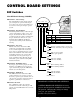
Step 5
Strip
3
/16" off the ends of the low voltage wire
and twist tightly. Attach these ends to the 18VAC
terminals located on the POWER IN terminal block
(see illustration at right). Be certain not to let the
exposed wires touch each other!
Insert one transformer wire into an 18VAC terminal.
Insert the other transformer wire into the remaining
18VAC terminal. The transformer wires can be
connected to the 18VAC terminals regardless of color.
Tighten set screws against exposed end of wires. A
dab of household petroleum jelly on each terminal will
help prevent corrosion.
RED
BLACK
RED
BLACK
Low Voltage Wire
from AC Transformer
SWITCH
MASTER INPUTS
GRN
WHT
BLUE
BRN
ORG
RED
BLK
J5J13
18 VAC SOLAR RELAY OUT
~ ~ - +
NC NORLY-COM
SLAVE INPUTS
GRN
WHT
BLUE
BRN
ORG
RED
BLK
J21J6J9J2J1
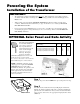
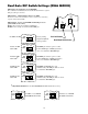
WARNING! DO NOT PLUG THE TRANSFORMER
INTO AN OUTLET DURING THIS STEP! THE
TRANSFORMER MUST ONLY BE PLUGGED INTO
AN OUTLET DURING STEP 7!!
Low Voltage Wire
from Transformer
or Solar Panel
PVC Pipe
Operator Power Cable
12 V Battery
Strain Relief
1
ON
2 3 4 5 6 7
1
ON
2 3 4
15
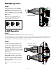
18VAC RECEIVER
BAT
+
SWITCH
FUSE
ALARM
SWITCH
DUAL
MODES
SET
LIMI
T
LEAR
N
TRANSMITTE
R
MODE
S
ON
OF
F
ON
OF
F
1 2 3 4 5 6 7
1 2 3 4
BAT
–
SOLAR RELAY OUT SLAVE INPUTS
GRN WHT BLUE BRN ORG RED BLKNC RLY-COM NO
MASTER INPUTS
GRN WHT BLUE BRN ORG RED BLK COM COM
CYCLE
CLOS
E
SAFET
Y
EXIT/
OPEN
SHADOW
LOOP
CLOS
E
EDGE
OPEN
EDGE
BLKGRN RED
+–~~
12'
10'
8'
14'
16'
GATE LENGT
H
800-543-GATE
www.gtoinc.com
GTO, Inc.
3121 Hartsfield Rd
Tallahassee, FL 32303