
User Guide

21
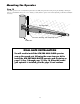
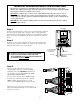
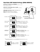
Step 4
Insert the stripped power cable wires into
the appropriate terminals on the MASTER
OPERATOR terminal block. The green wire
should be inserted into the GRN terminal, the
blue wire into BLU, the orange wire into ORG,
black wire into BLK, and the red wire into the
RED terminal.
Tighten the set screws against the end of
the wires. A dab of petroleum jelly on each
terminal will help prevent corrosion.
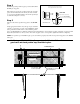
Correct
Wrong Wrong
Wire
Terminal
Block
Terminal
Block
Terminal
Block
Wire
Wire
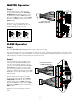
MASTER Operator
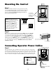
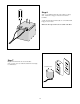
Step 6
Strip approximately
3
/16" of insulation from
each wire of the 50 foot power cable. Twist
each exposed wire tightly. Insert the second
operator power cable upward through the right
strain relief (if necessary, loosen the sealing
nut). Thread approximately 4" of wire into the
control box. Retighten strain relief (on the black
sheath of the power cable) until the power cable
locks into place.
Insert the stripped wires of the power cable
into the appropriate terminals on the SLAVE
OPERATOR terminal block. The green wire
should be inserted into the GRN terminal, the
blue wire into BLU, the orange wire into ORG,
black wire into BLK, and the red wire into the
RED terminal.
Tighten the set screws against the end of the
wires.
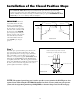
Step 5
Review the Installation Overview illustration on page 12 before proceeding.
Cut a slot into the driveway to accommodate PVC conduit (not provided). The buried conduit will protect the 40 foot power
cable from automobile tires, lawn mower blades, weed eaters, and grazing animals. Pull the 40 foot second operator power
cable through the conduit and secure them into the slot in the driveway.
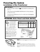
SLAVE Operator
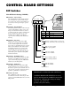
SWITCH
Power Cable from the
SLAVE operator arm
MASTER INPUTS
GRN
WHT
BLUE
BRN
ORG
RED
BLK
J5J13
SLAVE INPUTS
GRN
WHT
BLUE
BRN
ORG
RED
BLK
J21J6
Power cable from
MASTER operator arm
SWITCH
STALL FORCE
M
I
N
M
A
X
MASTER INPUTS
GRN
WHT
BLUE
BRN
ORG
RED
BLK
GRN
BLK
RED
RECEIVER
COM COM
CYCLE
CLOSE
SAFET
Y
EXI
T
OPEN
SHADOW
LOOP
CLOSE
EDGE
OPEN
EDGE
J11
J8J5J13
J12