Installation Manual for installing the GTO/PRO SW-4200 with the GTO/PRO SW-4000 in a dual application DC-SERIES ® DC-SERIES ® FOR PROFESSIONAL INSTALLATION ONLY! WARNING! This equipment is similar to other gate or door equipment and meets or exceeds Underwriters Laboratory Standard 325 (UL 325).
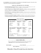
The GTO/PRO® 4000 Series Gate Operators are intended for use with vehicular swing gates. The operators can be used in Class I, Class II, Class III and Class IV applications. VEHICULAR GATE OPERATOR CLASS CATEGORIES Residential Vehicular Gate Operator-Class I: A vehicular gate operator (or system) intended for use in a home of one-to-four single family dwelling, or a garage or parking area associated therewith.
Table of Contents Gate Operator Class Categories ------------------------------------------------------------inside cover Units and Standards Conversion Chart ---------------------------------------------------inside cover PLEASE READ THIS FIRST! --------------------------------------------------page iii Important Safety Instructions -------------------------------------------------- page 1 KEEP THESE INSTRUCTIONS FOR FUTURE REFERENCE Disconnecting the Operator -------------------------------------------
DC-SERIES ® DC-SERIES ® PLEASE READ THIS FIRST! Thank you for purchasing a GTO/PRO® 4000/4200. When correctly installed and properly used, your GTO/PRO® 4000/4200 Operators will give you many years of reliable service. Please read the following information to ensure you have the correct system for your particular needs. This manual will enable you to properly install your GTO/ PRO® 4000/4200 Automatic Gate Operators.
IMPORTANT SAFETY INSTRUCTIONS Because automatic gate operators produce high levels of force, consumers need to know the potential hazards associated with improperly designed, installed, and maintained automated gate operator systems. Keep in mind that the gate operator is just one component of the total gate operating system. Each component must work in unison to provide the consumer with convenience, security, and safety. This manual contains various safety precautions and warnings for the consumer.
IMPORTANT SAFETY INSTRUCTIONS For The Consumer WARNING: To reduce the risk of injury or death: 1. READ AND FOLLOW ALL INSTRUCTIONS. Failure to meet the requirements set forth in the instruction manual could cause severe injury and/or death, for which the manufacturer cannot be held responsible. 2. When designing a system that will be entered from a highway or main thoroughfare, make sure the system is placed far enough from the road to prevent traffic congestion. 3.
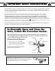
IMPORTANT SAFETY INSTRUCTIONS Entrapment Zones for a proper Pull-To-Open installation: Zone 1 – leading edge of the gate and the fence post. Zone 2 – between the gate and the gate post. Zone 3 – the path of the gate. Zone 4 – the space between the gate in the open position and any object such as a wall, fence, tree, etc. Zone 5 – pinch points between the opener and gate or post. II. During Installation 1. Install the gate opener on the inside of the property and fence line.
IMPORTANT SAFETY INSTRUCTIONS III. After Installation 1. Attach the warning signs (included) to each side of the gate to alert the public of automatic gate operation. It is your responsibility to post warning signs on both sides of your gate. If any of these signs or warning decals become damaged, illegible or missing, replace them immediately. Contact GTO for free replacements. 2. The gate is automatic and could move at any time, posing a serious risk of entrapment.
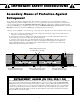
IMPORTANT SAFETY INSTRUCTIONS Secondary Means of Protection Against Entrapment As specified by Gate Operator Safety Standard, UL 325 (30A.1.1), automatic gate operators shall have an inherent entrapment sensing system, and shall have provisions for, or be supplied with, at least one independent secondary means to protect against entrapment. The GTO/PRO® 4000/4200 utilizes Type A, an inherent (i.e., built-in) entrapment sensing system as the primary type of entrapment protection.
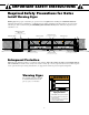
IMPORTANT SAFETY INSTRUCTIONS Required Safety Precautions for Gates Install Warning Signs Warning signs alert people of automatic gate operation and are required when installing the GTO/PRO® 4000/4200 Automatic Gate Operators. Furthermore, a walk-through gate must be installed if pedestrian traffic is expected near the vehicular gate. We recommend using the GTO Bulldog Pedestrian Gate Lock (Call the GTO Sales Department) for controlled access.
IMPORTANT SAFETY INSTRUCTIONS ! These warning labels should be found at the locations specified below. If any of them are missing, immediately contact GTO for replacements. DC SW-4000 SERIES C LIS TED US #xxxxxxx Conforms to UL 325 STANDARDS Maximum Gate: 1000 lb. (453.5 kg); 20 ft. (6.1 m) Voltage: 12 Vdc; Frequency: 0 Hz; Power: 60 W Class I, II, III and IV Vehicular Swing Gate Operator. Serial Number: XXXXXXXXXX TO MANUALLY OPEN AND CLOSE THE GATE: 1. Turn control box power switch OFF. 2.
SW-4000 Parts List Receiver (1) Battery (1) FF ON/O Transformer (1) Warning Signs (2) Control Box w/ Control Board (1) Gate Opener (6' Power Cable) GTO Transmitter(1) Customer Support Card Gate Bracket (1) Post Bracket (1) Closed Position Stop Plate (1) Post Pivot Bracket (1) Hardware 1/2" x 10" Carriage Bolt (2) 1/2" Washer (4) 1/2" x 2-3/4" Bolt (2) 1/2" Lock Nut (4) 3/8" x 3-3/4" Bolt (2) 3/8" Washer (3) 3/8" x 3-1/2" Clevis Pin (1) 3/18" Lock Nut (2) 3/8" x 1-3/4" Clevis Pin (1) Hairpin
SW-4200 Parts List Warning Signs (2) Gate Bracket (1) Post Bracket (1) Post Pivot Bracket (1) Closed Position Stop Plates (1) Hardware 1/2" x 10" Carriage Bolt (2) 1/2" Washer (4) 1/2" x 2-3/4" Bolt (2) 1/2" Lock Nut (4) 3/8" x 3-3/4" Bolt (2) 3/8" Washer (3) 3/8" x 3-1/2" Clevis Pin (1) 3/18" Lock Nut (2) 3/8" x 1-3/4" Clevis Pin (1) Hairpin Clip (2) 3/8" x 3/4" Bushing (2) 9 3/8" x 3/16" Bushing (2) 2" Receiver Mounting Screw (5) 8" Nylon Cable Tie (10) Gate Operator (50' power cable)
Other Materials You May Need Before You Start the Installation: Depending on the type of gate and fence post, you may need some additional materials/hardware. Some of these items can be found in the GTO/PRO Accessory Catalog. • Low voltage wire may be needed. Length depends upon the distance between the transformer power supply and the control box. See page 22, Powering the System and the Accessory Catalog for wire and solar charging panels.
Technical Specifications GTO/PRO® 4000/4200 AUTOMATIC GATE OPERATOR DRIVE • Low friction screw drive (linear actuator) rated for -5 ºF to +160 ºF (-28 ºC to +71 ºC). Use of heater bans on arm and control box will enhance performance in extreme cold temperatures. • Powered by a 12 V motor with integral case hardened steel gear reducer. Motor speed reduced to 260 rpm. Generates 820 ft.. lb. of torque at 12 V. • Maximum opening arc of 110º.
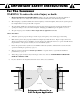
Installation Overview Pull-to-Open Gates (Gates Open into the Property) The diagram shown below is an example of a pull-to-open installation on a chain link fence and single gate. Mounting the operators on a masonry columns require special procedures; see Column Installation Information on page 38 if you intend to mount the operator on a column. Furthermore, if you have a push-to-open gates, you will need to purchase two pushto-open brackets (see Accessory Catalog) to properly configure your system.
Installing Mounting Hardware Installing the Post Bracket Assembly The post bracket is designed to work on a flat fence post. Fence posts must be at least 6” square in order to mount the post bracket. NOTE: The best method of attaching the post bracket to metal post is welding. Round wood posts (no smaller than 8” diameter) may be notched to create a flat surface for attaching the post bracket. If bolts are used to mount the post bracket, the bolts must completely penetrate the fence post.
Step 2: Position the post bracket on the fence post with the mounting holes centered over the scribe line. The post bracket should be flush with the edge of the fence post closest to the gate (see illustration). Mark the position of post bracket holes on the fence post. Step 3: Drill holes in fence post as marked using a 1/2" drill bit. Install the post bracket using the 1/2" x 10" carriage bolts, 1/ " washers, and lock nuts (provided).
Clevis Pin Step 5: Position the operator rear mount between post pivot bracket. Place a small bushing under the rear mount. Align the hole in rear mount, bushing and post pivot brackets and secure with the clevis pin and hair pin clip. Operator Hairpin Clip Clevis Pin Small Bushing Goes Under Rear Mount Front Mount Gate Bracket Step 6: Place a small bushing under the the front mount and attach the gate bracket to the front mount using the clevis pin and hairpin clip.
Step 8: Gate in the CLOSED POSITION 2" minimum Remove the clevis pin from the front mount and while supporting the gate operator, swing the gate and gate operator to the closed position. With the gate and gate operator in the closed position check the clearance and be sure that the gate operator is not binding at the post pivot bracket.
Mounting the Operator Step 10 Attach the operator to the securely bolted post bracket assembly and gate bracket using clevis pins, bushings, and hairpin clips, or optional Pin Locks (see Accessory Catalog). Verify that the operator is level and adjust the post bracket assembly if necessary.
Installation of the Closed Position Stops The GTO/PRO® 4000/4200 Gate Operators firmly hold the gates in the closed position using positive stops. The positive stops help stabilize the gate leaves in the closed position. To further enhance stability and security, we strongly recommended using an optional GTO/PRO® Automatic Gate Lock (see Accessory Catalog) with your dual gates. IMPORTANT: You need to determine which side of the driveway you will mount the control box.
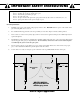
Step 2 Install a low profile ground stop (not provided) beneath the SLAVE gate stop plate. Closed Position Stop Plate mounted on the gate leaf that CLOSES FIRST Mount Vertically The ground stop needs to be positioned near the end of the gate as shown in Illustration A and may be made of metal or concrete and should be firmly secured in the ground (we recommend setting it in concrete).
Mounting the Control Box Step 1 15 Use mounting holes and screws provided to mount control box to a secure surface. ALARM FUSE 1 2 3 4 BAT– 800-543-GATE GTO, Inc. 3121 Hartsfield Rd Tallahassee, FL 32303 ON DUAL ON MODES BAT+ SWITCH 1 www.gtoinc.
MASTER Operator Step 4 ORG RED J5 BLK COM J11 COM CYCLE CLOSE SAFETY EXIT OPEN J8 Wrong SWITCH BRN Power cable from MASTER operator arm SHADOW LOOP Correct J13 BLUE MASTER INPUTS WHT Tighten the set screws against the end of the wires. A dab of petroleum jelly on each terminal will help prevent corrosion. GRN Insert the stripped power cable wires into the appropriate terminals on the MASTER OPERATOR terminal block.
Powering the System Installation of the Transformer IMPORTANT: • The transformer is designed and intended for indoor use. If the transformer can be plugged only into an outside electrical outlet, a weatherproof cover or housing (available at local electrical supply stores) must be used. • All low voltage wire used with the GTO/PRO® 4000/4200 Gate Operator must be 16 gauge dual conductor, multi-stranded, direct burial wire (see page 23 and the Accessory Catalog). Do not run more than 1000 feet of wire.
IMPORTANT INFORMATION ABOUT LOW VOLTAGE WIRE The only wire acceptable for use with GTO products is 16 gauge multi-stranded, low voltage, PVC sheathed wire. This particular gauge enables the transformer to provide an adequate charge through the control board to the battery at distances up to 1000 ft. DO NOT use telephone wire or solid core wire. Unlike multi-stranded wire, these types of wire are inadequate for use with your gate operator system.
Step 6 Strip 1/2" of insulation from the ends of the low voltage wire. Attach these stripped ends to the transformer terminals. A dab of household petroleum jelly on each terminal will help prevent corrosion. Make sure the exposed wires do not touch each other! Step 7 Transformer 24 SURGE PROTECTOR Plug the transformer into the electrical outlet. (Use of a surge protector with the transformer is strongly recommended.
CONTROL BOARD SETTINGS DIP Switches Main DIP Switch Settings (MODES) DIP Switch #1 - Soft Start/Stop The Soft Start/Stop feature slowly starts the gate as it begins to open and slows the gate as it comes to the closed position. This saves wear and tear on the gate and gate operator system. 1 2 3 4 5 6 7 ON ON 1 2 DIP Switch #2 - Warning Buzzer The Warning Buzzer alerts you when the gate operator is beginning to either open or close the gate. It sounds for the first 2 seconds in each direction.
Dual Gate DIP Switch Settings (DUAL MODES) DIP Switches #1 and #2 (Factory Set OFF/OFF) The combination of DIP Switches #1 and #2 will determine the sequence dual gates will open and close.
Setting the Closed Position Limits TURN CONTROL BOX ON Your GTO/PRO® 4000/4200 has two Limit Settings 1) OPEN Limit setting: (Gate in the OPEN POSITION / FACTORY SET NOT ADJUSTABLE) The open limit setting is the fully open position. 2) CLOSED Limit setting: (Gate in the CLOSED POSITION) To achieve optimum closed position, you are required to complete the following SEVEN STEPS: Step 1 Confirm that the power switch is in the ON position, and the gates are in the OPEN POSITIONS.
Step 7 Press the transmitter button and allow the gates to return to the fully open position. BOTH YOUR MASTER AND SLAVE GATE’S CLOSED POSITION LIMITS ARE NOW PROGRAMMED. TESTING YOUR CLOSED LIMIT SETTING: Press your entry transmitter and allow your gates to close. If CLOSED positions are not correct or need to be changed, you will need to CLEAR your CLOSED LIMIT settings and follow Steps 1-7 again.
Obstruction Sensitivity Potentiometer IMPORTANT: For safety reasons the obstruction setting or Stall Force on the GTO/PRO 4000 control board comes from the factory set at MIN (minimum). In many gate installations this setting will need to be adjusted to overcome the weight and size of the gates. 1 2 3 4 DUAL ON MODES 1 The Stall Force potentiometer on the control board operates like a volume control on a radio.
Connecting Additional Safety Devices Although GTO strongly recommends the use of additional safety devices, we do not endorse any specific brand names. Only use products that are certified and listed to be in compliance with any applicable UL standards (United Laboratories) and national and regional safety codes. Call GTO Sales at 1-800-543-4283 for information on compatible products for your specific application. The GTO/PRO® 4000 will ONLY accept accessory devices with normally open contact output.
Non-Contact Sensors (photo beams) If not installing a non-contact sensor skip to next section. PLEASE NOTE: Non-contact sensors are not included with the GTO/PRO® 4000. The GTO/PRO® 4000 can also accept "Safety" input from normally open "dry-contact" output devices such as photo beams connected to the SAFETY input terminal. Refer to the sensor manufacturer’s instructions for information about installing these devices on a vehicular gate.
Connecting Accessories If not connecting accessories skip to next section. The GTO/PRO® 4000 can accept NORMALLY OPEN CONTACT accessories, such as; Push Button Entry Devices and Key Pads. Refer to the sensor manufacturer’s instructions for information about installing these devices on a vehicular gate. Make sure the power to the operator is turned off before connecting safety device wiring to the terminal blocks. Unplugging the transformer does not turn power to the operator OFF.
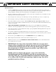
Push to Open Installation Determining The Mounting Position of The Post Bracket Assembly Swinging gates shall not open into public access areas! 1/2" x 3-3/4" Bolt A "Push-to-Open" gate opens out from the property. If you have a pull-to-open gate (gate opens into the property), return to page 13. Post Bracket In a PUSH-TO-OPEN installation the operators are installed while the gates are in the closed position.
Step 3 With the gate in the fully closed position and the operator retracted, swing the operator to the gate. Mark reference points for bolt holes on gate cross member through middle of gate bracket slots. The operator must be level. Drill 3/8" holes into the gate cross member as marked. Fasten gate bracket to cross member using (2) 3/8" x 3" bolts, washers, lock washers, and nuts. Attach the operator to the post bracket assembly and gate bracket using clevis pins, bushings, and hairpins clips.
Step 3 With the gate in the desired open position PRESS & HOLD the “SET LIMIT" button on the control board for 5 seconds. Step 4 Press the transmitter button and allow the gate to return to the closed position. YOUR GATE’S OPEN POSITION LIMIT IS NOW PROGRAMMED.
Maintenance & Troubleshooting If your gate operator does not function properly after it is installed, use this guide before calling the GTO Service Department. • On all gates weighing 250 lb. or more, routinely grease the ball bearing hinges at least 4 times a year; more frequently if the gates are near a coastal area. • Keeping a few mothballs in the control box will discourage insects from entering it and damaging the control board.
If the Operator is Working The Gate CLOSES Then Opens Again on its Own: 1. Check the position of the mounting brackets and readjust if necessary. 2. Check the gate for binding or hinge damage. The Gate OPENS Then Closes Again on its Own: 1. Check the position of the mounting brackets and readjust if necessary. 2. Check the gate for binding or hinge damage. VOLTAGE RATINGS 18 Vac Transformer ___________________________ 18.0 to 22.0 Vac 5 W Solar panel (single) _______________________18.0 to 22.
Repair Service If your GTO/PRO® 4000/4200 Gate Operators are not operating properly, please follow the steps below: 1. First use the procedures found in the Maintenance & Troubleshooting Guide (see page 36). 2. If you are unable to solve the problem, call the GTO Service Department at (800) 543-1236, or (850) 575-4144. Refer to the serial number (located on the control box cover) and date of purchase when calling for assistance. 3.
Column Installation Information IF THIS OPERATOR WILL BE USED WITH GATES THAT ARE MOUNTED ON MASONRY, BRICK, OR ROCK (etc.) COLUMNS: READ THE FOLLOWING CAREFULLY BEFORE PROCEEDING A. The simplest solution is to install the operator in a push-to-open configuration. The minimum clearance is easier to achieve and clearance is no longer a problem, since the operator will be pushing the gate away from the column instead of pulling it toward the column.
DC-SERIES ® DC-SERIES ® ACCESSORIES Solar Panel (FM123), (FM122) The Solar Panel is a 10 watt solar powered battery charger for use with the all GTO/PRO DC gate operator systems. Particularly suited for remote installations, each Solar Panel comes with tubular steel support, mounting clips, wire connectors, and 8 ft. of low voltage wire (see Low Voltage Wire for additional wire). The GTO/PRO® control board has clearly labeled terminal connections for easy installation of the Solar Panel.
ACCESSORIES Replacement Battery (RB500) Standard 12 volt, 7.0 amp-hour, maintenance-free battery for the GTO/PRO® 2000, GTO/PRO® 3000/3200, GTO/PRO® 4000/4200 gate operator systems. This is the only battery approved for use with the GTO/PRO® gate operator systems. Life expectancy is 3-5 years. Low Voltage Wire (RB509) The 16 gauge, multi-stranded, dual conductor Low Voltage Wire is for connecting the AC powered transformer, or the Solar Panel to the control board.