
User Guide

17
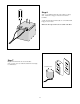
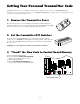
Use mounting
holes and screws
provided to mount
control box to a
secure surface.
1
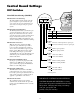
ON
2 3 4 5 6 7
1
ON
2 3 4
15
18VAC RECEIVER
BAT
+
SWITCH
FUSE
ALARM
SWITCH
DUAL
MODES
SET
LIMI
T
LEARN
TRANSMITTE
R
MODES
ON
OF
F
ON
OF
F
1 2 3 4 5 6 7
1 2 3 4
BAT
–
SOLAR RELAY OUT SLAVE INPUTS
GRN WHT BLUE BRN ORG RED BLKNC RLY-COM NO
MASTER INPUTS
GRN WHT BLUE BRN ORG RED BLK COM COM
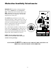
CYCLE
CLOS
E
SAFETY
EXIT
/
OPE
N
SHADOW
LOOP
CLOS
E
EDGE
OPE
N
EDGE
BLKGRN RED
+–~~
12'
10'
8'
14'
16'
GATE LENGT
H
800-543-GATE
www.gtoinc.com
GTO, Inc.
3121 Hartsfield Rd
Tallahassee, FL 32303
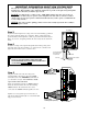
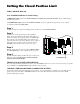
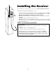
At this stage of the installation, the operator should be installed on
the gate and the closed position stop should be in place.
Check List
• The gate is plumb, level, and swings smoothly on its hinges.
• A plate or support was added for the gate bracket (if necessary).
• The operator is level and mounted on the centerline of the gate.
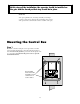
Mounting the Control Box
Step 1
Mount the control box using the screws (provided) or another
secure mounting method. The control box must be mounted at
least 3 feet above the ground to protect it from rain splash, snow,
etc., and at least 3 feet from an AC power source to prevent
electrical interference.