
User Guide

10
• Low friction screw drive (linear actuator) rated for -5 ºF to +160 ºF (-28 ºC to +71 ºC). Use of heater bans on arm and
control box will enhance performance in extreme cold temperatures.
• Powered by a 12 V motor with integral case hardened steel gear reducer. Motor speed reduced to 260 rpm. Generates
820 ft.. lb. of torque at 12 V.
• Maximum opening arc of 110º. Approximate opening time (90º): 20 seconds, depending on weight of gate.
POWER
• The system is powered by a 12 Vdc, 7.0 Ah, sealed, rechargeable acid battery.
• Battery charge is maintained by a 120 Vac, 18 Vac output transformer rectified to 14.5 Vdc (40 VA) through the GTO
control board. Blade-style control board fuse is rated for 25 A.
NOTE: The transformer should not be directly connected to any battery. Do not replace fuses
with higher ampere rated fuses; doing so will void your warranty and may damage your control board.
• Battery charge is maintained by GTO Solar Panel Charger: float voltage of 14.5 Vdc output from a 19
3
/
8" x 8
1
/
2"
silicon alloy panel. Generates minimum of 5 W at 300 mA. A gated diode on the control board prevents battery dis-
charge.
CONTROL
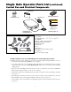
• GTO microprocessor-based control board is set for single leaf, pull-to-open gate installations. DIP switches can be
adjusted to accommodate an optional kit for push-to-open gates (see Accessory Catalog).
• Control board has temperature compensated circuits.
• A circuit on the control board regulates charging. "Sleep draw" is 40 mA; "active draw" is 5 to 9 A.
• Auto-memorization of digital transmitter code.
• GTO remote-mounted RF receiver tuned to 318 MHz.
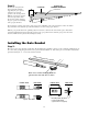
• Operator length with push-pull tube fully retracted is 46
1
/
4", mounting point to mounting point.
• Adjustable auto-close timer (15 to 120 s), and obstruction sensitivity.
• Power terminal bock accommodates a transformer and solar panels.
• DIP switches simplify setup of gate operator.
• Accessory terminal block fully compatible with push button controls, digital keypads, safety loops, etc.
• Control board allows connection of safety edge sensors and photoelectric sensors.
• Audio entrapment alarm sounds if unit encounters an obstruction twice while opening or closing.
OPERATIONAL CAPACITY
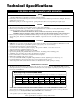
• The Gate Capacity Chart shows approximate cycles, per day, you can expect from the GTO/PRO® 4000 Automatic
Gate Operator when powered with a transformer. Actual cycles may vary slightly depending upon the type and condi-
tion of gate and installation.
NOTE: BALL BEARING HINGES SHOULD BE USED ON ALL GATES WEIGHING OVER 250 LB.
To determine the number of cycles the gate operator will perform using solar panels, please see the specifications
listed on page 19 or call (800) 543-1236 or (850) 575-4144 for more information.
* An operation cycle is one full opening and closing of the gate.
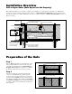
GTO/PRO® 4000 AUTOMATIC GATE OPERATOR
Technical Specifications
These specifications are subject to change without notice.
DRIVE
Gate Weight
Gate Length
Gate Capacity Chart GTO/PRO 4000
Estimated number of cycles are based on use with a transformer and one(1) 12 Volt battery on a single gate system.
20 ft.
16 ft.
12 ft.
8 ft.
135
140
145
150
300 lb.
130
135
140
145
400 lb.
125
130
135
140
500 lb.
120
125
130
135
600 lb.
115
120
125
130
700 lb.
110
115
120
125
800 lb.
105
110
115
120
900 lb.
100
105
110
115
1000 lb.