
User Guide
22
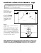
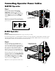
OPTIONAL Solar Panel and Gate Activity
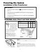
Powering the System
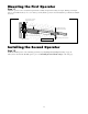
Installation of the Transformer
IMPORTANT:
• The transformer is designed and intended for indoor use. If the transformer can be plugged only into
an outside electrical outlet, a weatherproof cover or housing (available at local electrical supply stores)
must be used.
• All low voltage wire used with the GTO/PRO® 300/3200
®
Gate Operator must be 16 gauge dual
conductor, multi-stranded, direct burial wire (see page 23 and the Accessory Catalog). Do not run
more than 1000 feet of wire.
• If your gate is more than 1000 ft. from an ac power source, you will need to use from 10 to 30 watts
of solar charging power to charge the battery (see Accessory Catalog). Refer to the Solar Panel and
Gate Activity chart below.
Step 1
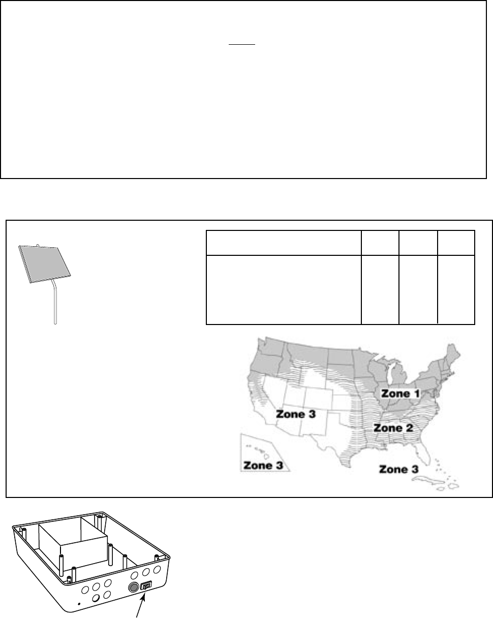
Make sure the power switch is OFF before proceeding to the next step.
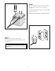
Step 2
Select the electrical outlet into which you will plug the transformer.
Measure the distance from this outlet to the control box following the
path where the wire will be laid. After you have measured how much
wire is needed, cut the wire to the appropriate length. (Not more than a
1,000 feet).
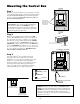
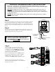
ON/OFF Switch
ON/OFF
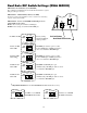
The table and map illustrate
the maximum number of
gate cycles to expect per day
in a particular area when
using from 10 to 30 watts of
solar charging power. (see
Accessory Catalog). The
figures shown are for winter
(minimum sunlight) and do not account for
the use of any accessory items. Accessories
connected to your system will draw
additional power from the battery.
NOTE: A maximum of 30 watts of
solar charging power can be connected
to the GTO/PRO® 3000/3200 Gate
Opener. Consult Solar Panel Installation
Instructions for further information.
Winter Ratings Zone 1 Zone 2 Zone 3
12 v dual gate (10 watts) solar charger 8 16 26
12 v dual gate (15 watts) solar charger 11 20 30
12 v dual gate (20 watts) solar charger 14 28 38
12 v dual gate (25 watts) solar charger 17 36 46
12 v dual gate (30 watts) solar charger 20 44 54