
User Guide
20
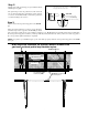
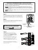
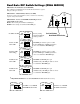
Step 2
Make sure the control box power switch is in the OFF
position. The ON/OFF Switch is located on the bottom of
the control box. Remove the control box cover and slide
the battery into position with its terminals to the RIGHT
(see illustration). Connect the BLACK battery wire to the
NEGATIVE (–) battery terminal. Connect the RED battery
wire to the POSITIVE (+) terminal. Pay close attention to
the color of the wires. If the wires are connected incorrectly,
the control board will be damaged. NEVER insert the
battery with the terminals to the left.
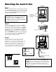
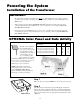
Mounting the Control Box
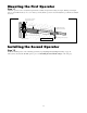
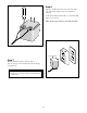
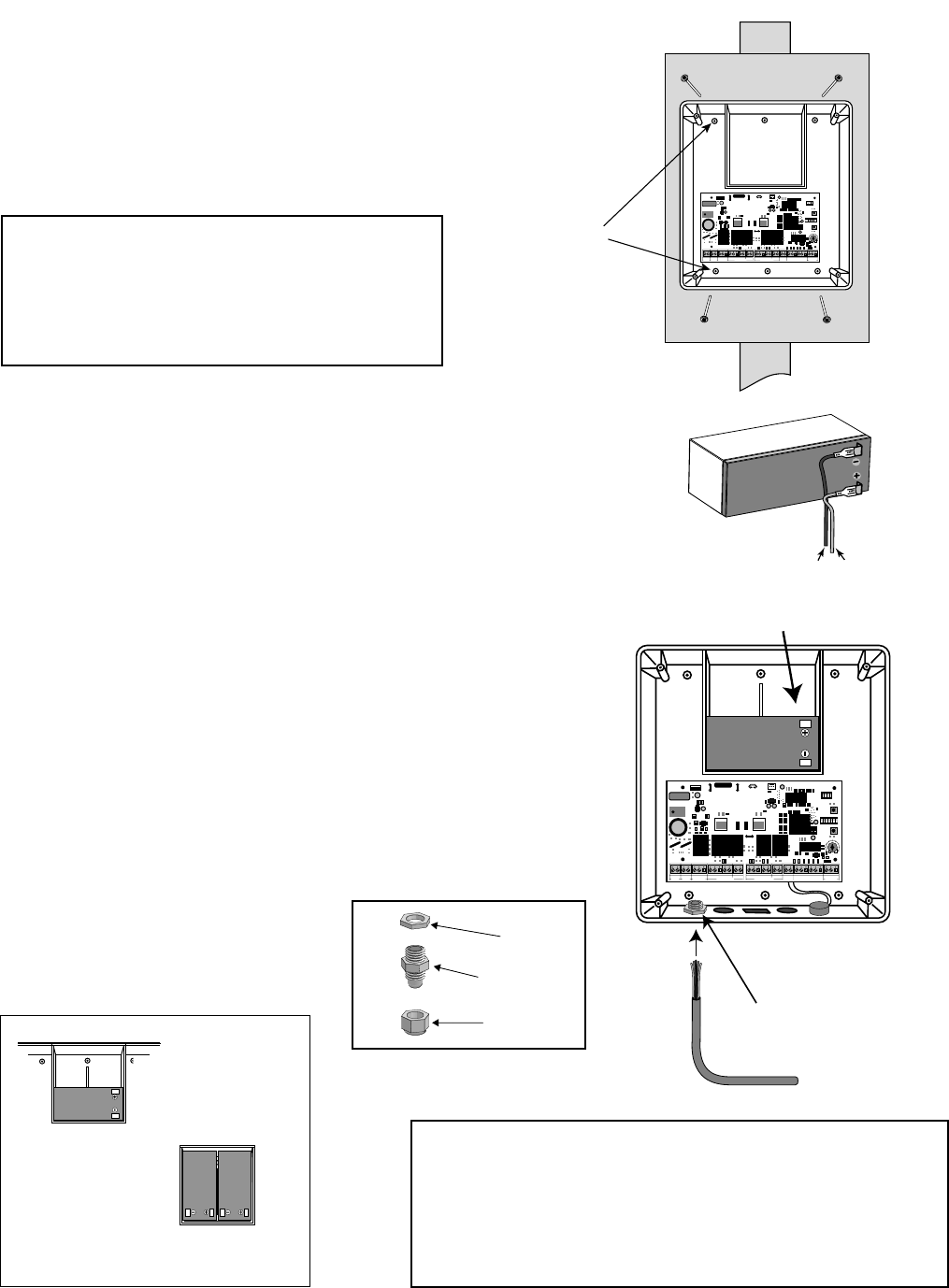
Step 3
Strip approximately
3
/16" of insulation from each
wire of the power cable. Twist each exposed wire
tightly (there are seven [7] wires inside the power cable
sheath). Loosen sealing nut on strain relief hub at
bottom of control box. Insert power cable into control
box through strain relief. Thread approximately 6"
of the power cable into the control box and retighten
sealing nut until the power cable locks into place.
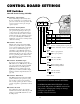
Step 1
Mount the control box using the screws (provided) or another
secure mounting method. The control box must be mounted at
least 3 feet above the ground to protect it from rain splash,
snow, etc., and at least 3 feet from an AC power source to
prevent electrical interference.
RED wire to POSITIVE (+) terminal
BLACK wire to NEGATIVE (—) terminal
RED
BLACK
Sealing Nut
Hub
Lock Nut
Strain Relief
NOTE: The battery that came with your GTO/PRO®
3000, MUST be placed in the top (horizontal) battery
slot with the terminals on the RIGHT. The extra
(vertical) battery slot is for an optional second battery.
An optional second battery can be used for solar and/or
high traffic applications, if needed..
Use mounting
holes and screws
provided to mount
control box to a
secure surface.
1
ON
2 3 4 5 6 7
1
ON
2 3 4
15
18VAC RECEIVER
BAT
+
SWITCH
FUSE
ALARM
SWITCH
DUAL
MODE
S
SET
LIMI
T
LEARN
TRANSMITTE
R
MODES
ON
OF
F
ON
OF
F
1 2 3 4 5 6 7
1 2 3 4
BAT
–
SOLAR RELAY OUT SLAVE INPUTS
GRN WHT BLUE BRN ORG RED BLKNC RLY-COM N O
MASTER INPUTS
GRN WHT BLUE BRN ORG RED BLK COM COM
CYCLE
CLOS
E
SAFETY
EXIT
/
OPE
N
SHADOW
LOOP
CLOS
E
EDGE
OPE
N
EDGE
BLKGRN RED
+–~~
12'
10'
8'
14'
16'
GATE LENGT
H
800-543-GATE
www.gtoinc.com
GTO, Inc.
3121 Hartsfield Rd
Tallahassee, FL 32303
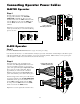
Operator Power Cable
12 V Battery (Included)
Strain Relief
1
ON
2 3 4 5 6 7
1
ON
2 3 4
15
18VAC RECEIVER
BAT
+
SWITCH
FUSE
ALARM
SWITCH
DUAL
MODE
S
SET
LIMI
T
LEARN
TRANSMITTE
R
MODE
S
ON
OF
F
ON
OF
F
1 2 3 4 5 6 7
1 2 3 4
BAT
–
SOLAR RELAY OUT SLAVE INPUTS
GRN WHT BLUE BRN ORG RED BLKNC RLY-COM NO
MASTER INPUTS
GRN WHT BLUE BRN ORG RED BLK COM COM
CYCLE
CLOS
E
SAFET
Y
EXIT
/
OPEN
SHADOW
LOOP
CLOS
E
EDGE
OPEN
EDGE
BLKGRN RED
+–~~
12'
10'
8'
14'
16'
GATE LENGT
H
800-543-GATE
www.gtoinc.com
GTO, Inc.
3121 Hartsfield Rd
Tallahassee, FL 32303
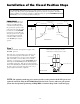
NOTE: The battery that came with your GTO/PRO® 3000 ,
MUST be placed horizontally battery with the terminals on the
RIGHT. If an optional second battery is needed, both batteries
must be placed vertically with terminals at the bottom. An
optional second battery can be used for solar and/or high traffic
applications, if needed..
Single Battery
Installed Horizontally
with terminals on the right.
Dual Batteries
Installed Vertically
with terminals on bottom
.