
User Guide

17
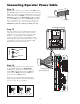
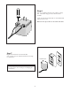
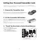
NOTE: The battery that came with your GTO/PRO® 3000 ,
MUST be placed horizontally battery with the terminals on the
RIGHT. If an optional second battery is needed, both batteries
must be placed vertically with terminals at the bottom. An
optional second battery can be used for solar and/or high traffic
applications, if needed..
Single Battery
Installed Horizontally
with terminals on the right.
Dual Batteries
Installed Vertically
with terminals on bottom.
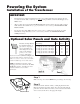
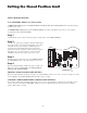
At this stage of the installation, the operator should be installed on
the gate and the closed position stop should be in place.
Check List
• The gate is plumb, level, and swings smoothly on its hinges.
• A plate or support was added for the gate bracket (if necessary).
• The operator is level and mounted on the centerline of the gate.
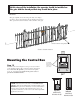
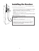
Mounting the Control Box
Step 13
Mount the control box using the screws (provided) or another
secure mounting method. The control box must be mounted at
least 3 feet above the ground to protect it from rain splash,
snow, etc., and at least 3 feet from an AC power source to
prevent electrical interference.
Use mounting
holes and screws
provided to mount
control box to a
secure surface.
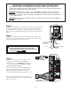
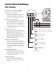
1
ON
234567
1
ON
234
15
18VAC RECEIVER
BAT
+
SWITCH
FUSE
ALARM
SWITCH
DUAL
MODES
SET
LIMIT
LEARN
TRANSMITTER
MODES
ON
OFF
ON
OFF
1 2 3 4 5 6 7
1 2 3 4
BAT
–
SOLAR RELAY OUT SLAVE INPUTS
GRN WHT BLUE BRN ORG RED BLKNC RLY-COM NO
MASTER INPUTS
GRN WHT BLUE BRN ORG RED BLK COM COM
CYCLE
CLOSE
SAFETY
EXIT/
OPEN
SHADOW
LOOP
CLOSE
EDGE
OPEN
EDGE
BLKGRN RED
+–~~
12'
10'
8'
14'
16'
GATE LENGTH
800-543-GATE
www.gtoinc.com
GTO, Inc.
3121 Hartsfield Rd
Tallahassee, FL 32303
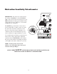
Closed Position Stop Plate
Gate In Closed Position
C
L