
User Guide

18
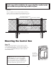
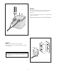
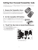
Step 15
Strip approximately
3
/16" of insulation from each wire of
the opener power cable. Twist each exposed wire tightly
(there are seven [7] wires inside the power cable sheath).
Loosen sealing nut on strain relief hub at bottom of
control box. Insert power cable into control box through
strain relief. Thread approximately 6" of the power cable
into the control box and retighten sealing nut until the
power cable locks into place.
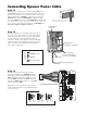
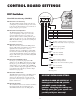
Step 16
Insert the stripped power cable wires into the
appropriate terminals on the OPENER terminal
block. The green wire should be inserted into the
GRN terminal, the blue wire into BLU, the orange
wire into ORG, black wire into BLK, and the red
wire into the RED terminal, white wire into WHT,
and brown wire into
BRN.
Tighten the set screws against the end of the wires.
A dab of petroleum jelly on each terminal will help
prevent corrosion.
Connecting Opener Power Cable
Sealing Nut
Hub
Lock Nut
Strain Relief
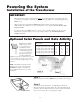
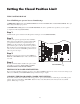
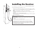
Step 14
Make sure the control box power switch is in the OFF position.
The ON/OFF Switch is located on the bottom of the control box.
Remove the control box cover and slide the battery into position
with its terminals to the RIGHT (see illustration). Connect the
BLACK
battery wire to the NEGATIVE (–) battery terminal.
Connect the
RED battery wire to the POSITIVE (+) terminal. Pay
close attention to the color of the wires. If the wires are connected
incorrectly, the control board will be damaged
. NEVER insert
the battery with the terminals to the left.
RED wire to POSITIVE (+) terminal
BLACK wire to NEGATIVE (–) terminal
RED
BLACK
Power Cable from the Operator
RECEIVER
SWITCH
MASTER INPUTS
GRN WHT BLUE BRN ORG RED BLK COM COM
CYCLE
CLOSE
SAFETY
EXIT/
OPEN
SHADOW
LOOP
CLOSE
EDGE
OPEN
EDGE
BLKGRN RED
STALL FORCE
M
I
N
M
A
X
Operator Power Cable
Strain Relief
Battery wires for
optional second battery.
12 Volt Battery
(included)
Space for optional
second 12 Volt battery
(see Accessory Catalog)
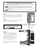
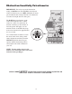
Correct
Wrong Wrong
Wire
Terminal
Block
Terminal
Block
Terminal
Block
Wire
Wire