
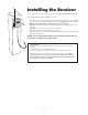
User Guide


28
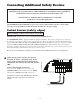
Connecting Additional Safety Devices
The GTO/PRO SW-1500 is equipped with built-in obstruction sensitivity. The operator is designed to stop and reverse
the gate for 2 seconds when it comes in contact with an obstruction. However, obstruction sensitivity, although functioning
properly, may not be sensitive enough to prevent bodily injury in some circumstances. To increase your protection against
entrapment, GTO recommends using some form of additional safety device. When installed, contact sensors must be
mounted in compliance with UL 325, Underwriters Laboratories safety standard for gate operators. Review page 5 for infor-
mation about mounting requirements for safety edges ("contact sensors").
Refer to the sensor manufacturer’s instructions for information about installing these devices on a vehicular gate.
PLEASE NOTE:
Contact sensors are not included with the GTO/PRO SW-1500.
The GTO/PRO SW-1500 will ONLY accept accessory devices with normally open dry contact output.
Any safety device that pulls more than 40 mA DC must have its own power supply.
Make sure the power switch to the operator
is turned off before connecting safety device
wiring to the terminal blocks. Unplugging the
transformer does not turn power to the operator
OFF.
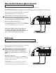
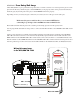
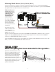
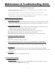
Contact Sensor Input Connection:
Connect one of the EDGE contact sensor wires to the
COMMON (COM) terminal and the other to the EDGE
terminal on the GTO/PRO SW 1500 control board.
Activation of a contact sensor while the gate is in motion
will cause the gate to stop and reverse for two (2)
seconds.
Contact Sensors (safety edges)
If not installing a contact sensor skip to next section.
Although GTO strongly recommends the use of additional safety devices, we do not endorse any specific
brand names. Only use products that are certified and listed to be in compliance with any applicable UL
standards (Underwriters Laboratories) and national and regional safety codes.
Call GTO Sales at 1-800-543-4283 for information on compatible
products for your specific application.
1
ON
2 3 4
15
CHARGING
POWER
STATUS
RF
PULL-PUSH
MODE1
MODE2
LOCK/BEACON
OFF 120
MIN MAX
STALL FORCE
CLOSE TIME
SET
LIMI
T
LEARN
REMOTE
AU
X OUT
SOLAR
PA
NEL
18VAC
RCVR
GRN
BLK
RED
EXIT
SAFETY
EDGE
CYCL
E
COMMON
LINK
Wires from Contact Sensor