Installation Manual for the ¨ + LIS TED 75 Series Automatic Gate Operator for Vehicular Swing Gates WARNING! RB918 This product meets and exceeds the requirements of UL 325, the standard which regulates gate operator safety, as established and made effective March 1, 2000, by Underwriters Laboratories Inc. , INC. 3121 Hartsfield Road • Tallahassee, Florida, USA 32303 Telephone (800) 543-GATE or (850) 575-0176 • Fax (850) 575-8912 • www.gtoinc.
GTO/PRO 1000 series automatic gate operators are intended for use with vehicular swing gates. These operators can be used in Class I, Class II and Class III applications. VEHICULAR GATE OPERATOR CLASS CATEGORIES Residential Vehicular Gate Operator-Class I: A vehicular gate operator (or system) intended for use in a home of one-to-four single family dwelling, or a garage or parking area associated therewith.
TABLE OF CONTENTS Safety Instructions -------------------------------------------------------------------------- page 1 Technical Specifications ------------------------------------------------------------------- page 8 Single Gate Operator Installation ------------------------------------------------------- page 9 Powering The System --------------------------------------------------------------------- page 20 Solar Panels and Gate Activity -----------------------------------------------------------------
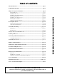
IMPORTANT SAFETY INSTRUCTIONS Because automatic gate operators produce high levels of force, all system designers, installers, and consumers have an obligation to know the potential hazards associated with improperly designed, installed, or maintained gate operator systems. Keep in mind that the gate operator is just one component of the total gate operating system. Each component must work in unison to provide the consumer with convenience, security, and safety.
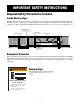
IMPORTANT SAFETY INSTRUCTIONS For The System Designer WARNING: To reduce the risk of injury or death: 1. READ AND FOLLOW ALL INSTRUCTIONS. 2. This operator is intended for use only on vehicular gates. Pedestrians must be supplied with a separate walkthrough gate (see Entrapment Protection illustration on page 6). 3. When designing a system that will be entered from a highway or main thoroughfare, make sure the system is placed far enough from the road to prevent traffic congestion. 4.
IMPORTANT SAFETY INSTRUCTIONS IMPORTANT SAFETY INSTRUCTIONS for the Installer III. After Installation 1. Review ALL safety instructions with the consumer/end user and explain the basic operation and safety systems of the entire gate operator system, including disconnecting the operator for manual operation of the gate. 2. Attach the warning signs (included) to each side of the gate to alert public of automatic gate operation. Take a photo of warning signs installed on gate.
IMPORTANT SAFETY INSTRUCTIONS Secondary Means of Protection Against Entrapment As specified by Underwriters Laboratories Inc. UL 325 (30A.1.1), automatic gate operators shall have provisions for, or be supplied with, at least one independent primary and one independent secondary means to protect against entrapment. GTO gate operators utilize Type A, an inherent (i.e., built-in) entrapment sensing system, as the primary type of entrapment protection.
IMPORTANT SAFETY INSTRUCTIONS For The Consumer/End User WARNING: To reduce the risk of injury or death: 1. READ AND FOLLOW ALL INSTRUCTIONS. 2. Distribute and discuss copies of the IMPORTANT SAFETY INSTRUCTIONS section of this manual with all persons authorized to use your gate. 3. Always keep people and objects away from the gate and its area of travel. NO ONE SHOULD CROSS THE PATH OF THE MOVING GATE. 4. Your automatic gate is not for pedestrian use.
IMPORTANT SAFETY INSTRUCTIONS Required Safety Precautions for Gates Install Warning Signs Warning signs alert people of automatic gate operation and are required when installing the GTO/PRO 1000 and series gate operators. Furthermore, a walk-through gate must be installed if pedestrian traffic is expected near the vehicular gate. We recommend the GTO Bulldog Pedestrian Gate Lock (see Accessory Catalog) for controlled access.
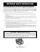
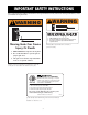
IMPORTANT SAFETY INSTRUCTIONS These warning labels should be found at the locations specified below. If any of them are missing, immediately contact your installer for replacements. ! ! WARNING WARNING MOVING GATE Can Cause Injury or Death 1. 2. 3. Moving Gate Can Cause Injury Or Death KEEP CLEAR! Gate may move at any time. Do not allow children to operate gate or play in gate area. This gate is for vehicles only. Pedestrians must use separate entrance.
Technical Specifications GTO/PRO 1000 Series Swing Gate Operators DRIVE o o • Low friction screw drive (linear actuator) rated for -30 F to +200 F. Powered by a 12 V motor with integral case hardened steel gear reducer. Motor speed reduced to 220 rpm. Generates 330 ft.. lb. of torque at 12 V; • 90º opening time: 15 s to 17 s, depending on weight of gate. POWER • The GTO/PRO 1000 system is powered by a 12 Vdc, 7.
Parts Identification Single Gate Operator and Hardware 4 1/2" x 4 1/2" Setback Template (1) Gate Opener (1) embly t Ass Bracke Manual Post lation of the ation the Instal Install 6 in See 5 and pages ® ERS OPEN GATE MATIC AUTO Gate Bracket (1) 4 1/2' Power Cable (1) Customer Support Card (1) Closed Position Stop Plate (1) Post Bracket (2) Post Pivot Bracket (1) 8" Nylon Cable Tie (14) Hardware 3/8" x 8" Bolt (4) 3/8" Washer (9) 3/8" x 3" Bolt (2) 3/8" Lock Washer (7) 2" Receiver Mounting Screw (1)
Single Gate Operator Parts List Control Box and Electrical Components Battery (1) Receiver (1) Transformer (1) GTO Transmitter(1) ! WARNING Moving Gate Can Cause Injury Or Death Control Box Lid (1) Control Box (1) 1. KEEP CLEAR! Gate may move at any time. 2. Do not allow children to operate gate or play in gate area. 3. This gate is for vehicles only. Pedestrians must use a separate entrance.
Installation Overview Pull-to-Open Gates (Gate Opens into the Property) The diagram below is an example of a pull-to-open installation on a chain link fence and single gate. If you are installing a push-to-open gate system, see Push-to-Open Installation starting on page 30. Mounting the operator on a masonry column requires special procedures; see Column Installation Information on page 35 before proceeding.
Determining The Mounting Position of The Post Bracket Assembly and The Gate Bracket Join the post bracket assembly using the 3/8" x 2" bolt in the center holes as shown. Fasten a 3/8" washer and nut on the end of the bolt. DO NOT overtighten nut because the post pivot bracket will need to be adjusted later.
Step 6 Study the 4 1/2" x 4 1/2" setback template (see insert) provided with this manual. Once you are familiar with its illustrations, cut and save the template from the insert. The template will determine the correct position of the post pivot bracket before mounting the operator on the fence post. Remove hairpin, clevis pin, and washer from operator and close the gate. Rest disconnected operator on cross member of gate.
Installation of Mounting Hardware The post bracket position determines both the leverage and efficiency of the operator, and the clearance between the operator and the gate in the open and closed positions. The post bracket is designed with a curvature that works well with installations on both round and square fence posts. Since the post bracket carries the entire back thrust of the active operator, it is absolutely necessary that it be mounted with bolts that completely penetrate the fence post.
Installing The Post Bracket Assembly and Gate Bracket Step 7: Mark the holes in the middle of the bracket slots so there will be some room for adjustment when mounting the post bracket assembly and the gate bracket on the fence post and gate cross member. Then remove the operator and brackets from the fence and gate. Step 8: Drill 3/8" holes in the fence post as marked.
Mounting the Operator Step 11: Attach the operator to the securely mounted post bracket assembly and gate bracket using the clevis pins and hairpin clips or optional Master Pin Locks (see Accessory Catalog). Check the level of the operator, and adjust the post bracket assembly if necessary. AUTOMAT IC GATE OPENER ® S Installation of the Positive Stops (Open and Closed Positions) The positive stops hold the gate firmly in the open and closed positions.
At this stage of the installation, the operator should be installed on the gate and the open and closed position stops should be in place. Check List • The gate is plumb, level, and swings smoothly on its hinges. • After measuring with the 4 1/2" x 4 1/2" setback template, the post bracket assembly was bolted to the fence post. • A plate or support was added for the gate bracket (if necessary). • The operator is level and mounted on the centerline of the gate.
Mounting the Control Box Step 14 Mount the control box using the nylon cable ties (provided) or another secure mounting method. The control box must be mounted at least 3 feet above the ground to protect it from rain splash, snow, etc., and at least 3 feet from an ac power source to prevent electrical interference. Step 15 AUTO CLOSE + BATT STATUS PWR. SW. – INERTIA 12 V Battery . OBSTR SENS.
® AUTOMATIC GATE OPENERS Step 17: Push-Pull Tube Carefully insert the power cable plug into the coupling at the rear of the operator. Turn the plug until it aligns with the pins in the coupling. Push the plug into the coupling until it stops. Finger tighten the sleeve nut to lock the plug in position. Replace the control box cover and fasten it with (4) screws. Turn the control box power switch ON. The control board will energize in approximately 15 seconds.
Powering The System IMPORTANT: • The GTO transformer is intended for indoor use. If the transformer can only be plugged into an outside electrical outlet, a weatherproof housing or cover (available at local electrical supply stores) must be used. • All low voltage wire for powering the GTO/PRO must be 16 gauge dual conductor, multi-stranded, direct burial wire (see Accessory Catalog). Do not exceed 1000 ft. of wire. • If your gate is more than 1000 ft.
IMPORTANT INFORMATION ABOUT LOW VOLTAGE WIRE The only wire acceptable for use with GTO products is 16 gauge multi-stranded, low voltage, PVC sheathed wire. This particular gauge enables the transformer to provide an adequate charge through the control board to the battery at distances up to 1000 ft. DO NOT use telephone wire or solid core wire. Unlike multi-stranded wire, these types of wire are inadequate for use with your gate operator system.
Step 26: Strip 1/2" off the ends of the low voltage wire and attach ends to the transformer terminals; red lead to (RED), black lead to (BLK). A dab of household petroleum jelly on each terminal will help prevent corrosion. We suggest crimping a spade tongue terminal (not provided) to the end of each wire before attaching it to the transformer. Be certain wire ends do not touch each other! Spade Tongue Terminal (not provided) Red Black Step 27: Plug in the transformer.
CONTROL BOARD SETTINGS DIP switches The four DIP switches on the control board match the operator with the type of gate on which it is mounted. For example, gates may pull-to-open or push-to-open. Prior to packaging, the GTO/PRO 1000 control board was configured for single swing gates that pull-to-open (open into the property). If your gate type matches this configuration, you DO NOT need to adjust the DIP switches; proceed to the Potentiometers section on the next page.
Potentiometers The three (3) potentiometers on the control board operate like a volume control on a radio. They control the auto close timer, inertia, and obstruction sensitivity of the operator. Use a small slotted screwdriver to turn the arrow in the center of the potentiometer. Clockwise rotation increases the setting (MAX). Counterclockwise rotation decreases the setting (MIN). AUTOCLOSE 60 OFF 120 INERTIA MIN MAX MAX 2 3 MIN 1 ON PULL/PUSH SNGL/DUAL SEQ1 SEQ2 4 OBSTRUCT SENS.
Setting Your Personal Transmitter Code All GTO transmitters are set to a standard code at the factory and are ready to activate your automatic gate operator. For your safety and security, however, we strongly recommend that you replace the factory setting with your own personal code. Follow the directions below: 1. Remove the Transmitter Cover Grasp the sides of the access cover and slide it away from the transmitter button (see illustration).
Mounting the Receiver Use the transmitter to check the range of the receiver before permanently mounting it. Consider the following when mounting the receiver: • Receiver cable length is 10 feet (receivers with a longer cable are available as special order items; call the GTO Sales Department). NEVER splice receiver cable! • Run the cable through PVC conduit to protect it from damage. • DO NOT run cable through metal conduit because the receiver signal range will be decreased.
Connecting Additional Safety Devices The GTO/PRO 1000 series operators are equipped with built-in obstruction sensitivity. The operator is designed to stop and reverse the gate for 2 seconds when it comes in contact with an obstruction. However, obstruction sensitivity, even when properly adjusted, may not be sensitive enough to prevent bodily injury in some circumstances. To augment your protection against entrapment, GTO suggests using safety edge sensors or photoelectric sensors.
Compatible Safety Devices Although GTO strongly recommends the use of safety devices, we do not endorse any specific brand names. Below is a list of some products compatable with GTO operators systems, some of which require their own power supply. Check with the individual manufacturer for specific power needs. Only use products that are certified and listed to be in compliance with national and regional safety codes. Safety Edges Miller Edge, Inc.
Connecting Accessories Make sure the control box power switch is OFF before connecting accessories. The ACCESSORY terminal block is the connection point for accessories such as push buttons, safety loops, intercoms, etc. The ACCESSORY terminal marked GRN (green) is the common ground for all accessories. GRN is paired with the terminals shown below when connecting accessories to the control board. WHT (white) used with GRN (green): Functions as a normally open contact.
Push to Open Installation Swinging gates shall not open into public access areas! A "Push-to-Open" gate opens out from the property. A Push-to-Open Kit is required for this type of installation (see Accessory Catalog). If you have a pull-to-open gate (gate opens into the property), return to page 12; step 5. The operator is installed while the gate is in the closed position. Step PTO-1: With the gate closed, adjust the post bracket assembly and the gate bracket until the operator is level.
Step PTO-3: With the gate in the fully closed position and the operator retracted, swing the operator to the gate. Mark reference points for bolt holes on gate cross member through middle of gate bracket slots. The operator must be level. (Some vertical adjustment is possible by sliding the post bracket assembly up and down.) Drill 3/8" holes into the gate cross member as marked. Fasten gate bracket to cross member using (2) 3/8" x 3" bolts, washers, lock washers and nuts.
Maintenance and Troubleshooting Guide If your gate operator does not function properly after it is installed, use this guide before calling the GTO Service Department. • On all gates weighing 250 lb. or more, routinely grease the ball bearing hinges at least 4 times a year; more frequently if the gates are near a coastal area. • Keeping a few mothballs in the control box will discourage insects from entering it and damaging the control board.
If the Operator is Working The Gate CLOSES Then Opens Again on its Own: 1. Check the position of the mounting brackets and readjust if necessary. 2. Check the gate for binding or hinge damage. 3. Check the position of the stroke adjustment knob. The Gate OPENS Then Closes Again on its Own: 1. Check the position of the mounting brackets and readjust if necessary. 2. Check the gate for binding or hinge damage. 3. Check the position of the stroke adjustment knob.
Warranty and Repair Service If the GTO gate operator system is not operating properly, please follow the steps below: 1. First, check the Troubleshooting Guide (see page 32). 2. Call your dealer or installer for assistance. 3. If your dealer or installer is unable to resolve the problem, call the GTO Service Department at (850) 575-4144 to discuss the problem with a service technician. Refer to the serial number (located on the control box cover) and date of purchase when calling for assistance. 4.
Column Installation Information READ THE FOLLOWING CAREFULLY BEFORE INSTALLING THE GTO/PRO 1000 AND GTO/PRO 1200 ON GATES THAT ARE MOUNTED ON COLUMNS MADE OF MASONRY, BRICK, ROCK, etc. Attaching a gate operator to a gate mounted on a masonry column requires special procedures. Here's how to check your installation to minimize problems: Open the gate to the 90º position, then measure the distance between the back of the gate and the face of the column.
GTO/PRO Dual Gate System Installation Second Unit Parts List GTO Operator (1) Post Pivot Bracket (1) ® ERS OPEN GATE MATIC AUTO Gate Bracket (1) ) ble (1 25' r Ca Powe Strain Relief (1) Closed Position Stop Plate (1) Customer Support Card (1) Post Bracket (2) 8" Nylon Cable Tie (6) Hardware (Actual Size) 3/8" x 8" Bolt (4) 3/8" Washer (9) 3/8" x 3" Bolt (2) 3/8" Lock Washer (7) 3/8" x 2" Bolt (1) 5/16" Washer (1) 5/16" x 1-3/4" Bolt (1) 3/8" Nut (7) 3/8" x 1-1/8" Clevis Pin (2) 5/16" Nut (1)
Installing the Second Unit The diagram below is of a dual gate, pull-to-open (open-in) installation on a chain link fence and gates. "Pull-to-Open" dual gates open into the driveway. If you are installing a "Push-to-Open" gate system see "Pushto-Open Installation" starting on page 30.
Step D-5: Closed Position Stop Plate mounted on the gate leaf that CLOSES FIRST Mount Vertically Attach the closed position stop plate vertically to the inside bottom of the gate that will close first. When the gate is in closed position, the positive stop plate should rest against the ground stop installed in Step D-4. SIDE VIEW Closed Position Stop Plate Low Profile Ground Stop in Center of Driveway FRONT VIEW Connecting the Second Operator to the Control Board Step D-6: Turn power switch OFF.
Step D-9: Cut slot into driveway and lay PVC conduit in this slot. Pull the 25 foot power cable for the second operator through the conduit (see Illustration B on page 37). ® AUTOMATIC GATE OPENERS Step D-10: Carefully insert the power cable plug into the coupling at the bottom of the operator housing. Turn the plug until it aligns with the pins in the operator coupling. Tighten the sleeve nut to lock the plug into place.
Step D-13 BOTH OPERATORS OPEN SIMULTANEOUSLY BOTH OPERATORS CLOSE SIMULTANEOUSLY If SEQ1 is set to ON, and SEQ2 is set to OFF, the FIRST OPERATOR and SECOND OPERATOR open and close simultaneously. PULL/PUSH SNGL/DUAL SEQ1 SEQ2 1 2 3 4 SEQ2 = OFF ON SEQ1 = ON OBSTRUCT SENS.
® AUTOMATIC GATE OPERATORS AccessoriesfromGTO,Inc. Available through your dealer.
Accessories Available Through Your Dealer GTO Digital Keypad (F300) 1 2 3 4 5 6 7 8 9 The weatherproof digital keypad can be easily installed as a wired or wireless keypad for all GTO swing and slide gate operators, and as a wired keypad for the Bulldog Pedestrian Gate Lock. It can be programmed to recognize fifteen different personal identification number (PIN) codes. Each code is face programmable with additional security features built in. Requires 3 AA batteries (not included).
ACCESS-ories Column Mount Lock Receiver (433IH) Master® Pin Lock (RB975) For mounting the Automatic Gate Lock or Bulldog Pedestrian Lock in areas with limited space between the gate and post, such as brick columns or walls. Master® Pin Lock (FM320) for GTO/PRO 1000/1200 for GTO/PRO 2000/2200 Column Mount Bracket (349IH) For column installation of the GTO/ PRO 1000 series operators. Designed for mounting the Post Pivot Bracket on masonry columns or any flat surface.
ACCESS -ories Operator Solar Panel (FM123 ) - Improved, Amorphous Silicon This 10 watt solar panel is a battery charger for use with GTO/PRO Low Voltage Automatic Gate Operator systems. Particularly suited for remote installations, the solar panel comes with tubular steel support, mounting clips, wire connectors, and 8 ft. of low voltage wire (for longer lengths, see RB509). All GTO low voltage operators are pre-wired for solar panels.
Installation Check List The installation of this operator conforms to CLASS __________. The installer verifies that (each item except safety edges must be checked): ___ Recommended safety edges were installed. ___ Customer was informed that this gate is for vehicular use ONLY. Pedestrians MAY NOT use this gate. ___ A separate gate or entrance was installed for pedestrian use. ___ Closed position stop plate was securely fastened.