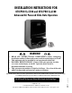
INSTALLATION INSTRUCTIONS FOR GTO/PRO SL-5100 and GTO/PRO SL-6100 Advanced AC Powered Slide Gate Operators LI US STED WARNING! • READ ALL INSTRUCTIONS COMPLETELY before attempting installation and use; failure to do so may result in serious injury or death! • This unit must only be installed by an experienced technician! • DANGER: HIGH VOLTAGE! Contact with gate operator circuitry can cause serious injury or death! Operator power must be disconnected before servicing! • This gate operator produces a hig
The GTO/PRO SL-5100 and SL-6100 automatic slide gate operators are intended for use with vehicular slide gates. The operators can be used in Class I, II, III, and IV applications. VEHICULAR GATE OPERATOR CLASS CATEGORIES Residential Vehicular Gate Operator-Class I: A vehicular gate operator (or system) intended for use in a home of one-to-four single family dwelling, or a garage or parking area associated therewith.
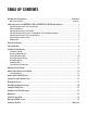
TABLE OF CONTENTS Gate Operator Class Categories ....................................................................................................................Inside Cover Metric Conversion Chart .......................................................................................................................................................Inside Cover Safety Instructions for the GTO/PRO-SL-5100 and GTO/PRO SL-6100 Slide Gate Operators .......................................
Important Safety Instructions SAFETY INSTRUCTIONS FOR THE GTO/PRO SL-5100 AND GTO/PRO SL-6100 SLIDE GATE OPERATORS Because automatic gate operators produce high levels of force, all system designers, installers, and consumers have an obligation to know the potential hazards associated with improperly designed, installed, or maintained gate operator systems. Keep in mind that the gate operator is just one component of the total gate operating system.
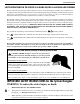
Important Safety Instructions IMPORTANT SAFETY INSTRUCTIONS for the Installer WARNING–To reduce the risk of injury or death: I. Before Installation 1. READ AND FOLLOW ALL INSTRUCTIONS. 2. Verify this operator is proper for the type and size of gate, and its frequency of use. 3. Make sure that the gate has been properly installed and slides freely in both directions. Repair or replace all worn or damaged gate hardware prior to installation.
Important Safety Instructions IMPORTANT SAFETY INSTRUCTIONS Specific to Secondary Means of Protection Against Entrapment As specified by Underwriters Laboratories Inc. UL 325 (30A.1.1), automatic gate operators shall have provisions for, or be supplied with, at least one independent primary and one independent secondary means to protect against entrapment. GTO gate operators utilize Type A, an inherent entrapment sensing system, as the primary type of entrapment protection.
Important Safety Instructions IMPORTANT SAFETY INSTRUCTIONS for the Consumer/End User WARNING: To reduce the risk of injury or death: 1. READ AND FOLLOW ALL INSTRUCTIONS. 2. Distribute and discuss copies of the IMPORTANT SAFETY INSTRUCTIONS manual with all persons authorized to use your gate. SAVE THESE INSTRUCTIONS. 3. Always keep people and objects away from the gate and its area of travel. NO ONE SHOULD CROSS THE PATH OF THE MOVING GATE. 4. Your automatic gate is not for pedestrian use.
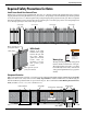
Important Safety Instructions Required Safety Precautions for Gates Install Screen Guard Over Gate and Fence Injuries may occur when people put their hands, arms, legs, etc., through openings in the grill when the gate is operated, trapping them between the grill and the fence post (or fence). All openings of a horizontal slide gate must be guarded or screened to prevent a 21/4” diameter sphere from passing through openings anywhere in the gate.
Important Safety Instructions Warning Labels These warning signs and labels should be found at the locations specified below. If any of them are missing, immediately contact your installer for replacements. ! WARNING ! WARNING Moving Gate Can Cause Injury Or Death 1. KEEP CLEAR! Gate may move at any time. 2. Do not allow children to operate gate or play in gate area. 3. This entrance is for vehicles only. Pedestrians must use a separate entrance. 4. Read the owner's manual and safety instructions. 5.
TECHNICAL SPECIFICATIONS for the GTO/PRO SL-5100 & SL-6100 AC Gate Operators Motor • GTO/PRO SL-5100: 1/2 hp GTO-Leeson 1625 rpm TEFC; C-Face connection; 115 V, single phase. • GTO/PRO SL-6100: 1 hp GTO-Leeson 1600 rpm TEFC; C-Face connection; 115 V, single phase. Gear Reducer • Totally enclosed 30:1, 60 series reducer, with vertical motor flange. • Machine cut bronze gears run in an oil bath. • Oil temperature range: –22 °F to 806 °F (–30 °C to 430 °C).
PARTS IDENTIFICATION GTO/PRO SL-5100 and GTO/PRO SL-6100 AC Powered Slide Gate Operators Receiver (1) ® AUTOMATIC GATE OPERATORS ! WARNING GTO Transmitter (1) Moving Gate Can Cause Injury Or Death Gate Warning Signs (one for each side) Manual Operation of Gate STANDARDS Conforms to UL 325 IMPORTANT SAFETY INSTRUCTIONS GTO/PRO SL-5100 & GTO/PRO SL-6100 AC Powered Slide Gate Operators LISTED ® 9901178 Installation Instructions for or close the gate, To manually open Release and push step on Foot Pe
INSTALLING THE GATE OPERATOR THIS UNIT MUST ONLY BE INSTALLED BY AN EXPERIENCED TECHNICIAN. Preparation of the Gate Before installing the GTO/PRO slide gate operator, make sure: • • • • • the gate is properly installed. the gate is plumb, level, and moves freely. the gate does not bind or drag on the ground. the gate is screened if necessary (see page 5.) roller guards are installed (see page 5.
Using the Mounting Template The mounting template (see insert) is designed to simplify mounting the operator. It provides the installer with the proper locations for running power and accessory wiring conduits. The template is also marked with the correct distance between the operator mounting holes and shows the installer how to position the operator for the correct clearance between the housing and the gate. NOTE: The operator must be securely mounted on a level concrete pad.
Removing the Operator Housing Before you can gain access to the operator frame and its mounting holes, the housing will have to be removed from the operator. 1. Remove the (2) 3/8” chrome acorn nuts and (2) 3/8” washers from the operator housing (this hardware is located on the front of the housing). Lift the housing off the operator and set it aside. Acorn nuts Washers Mounting the Operator 1. Lift the operator and align its mounting holes over the 1/2” diameter concrete mounting anchors.
4. Chain adjuster bolts: adjust outside nut until desired chain tension is achieved. Tighten inside nut to secure bolt (see illustration below). 5. Release foot pedal to re-engage chain sprocket. Chain Bracket Chain Bracket Sprocket Roller Guides ! WARNING • Fingers, hands, and loose clothing may be dragged into chain sprockets. • Fingers and hands can be injured by rotating sprockets. • Keep hands, fingers, and loose clothing away from chain and sprockets.
ADJUSTING THE LIMIT SWITCHES The limit switches determine how far the gate travels to open and close. The closer the limit nut is to the limit switch, the less distance the gate will travel to open or close. Adjust the limit switches by moving the limit nuts. MAKE SURE THE OPERATOR POWER IS OFF BEFORE ADJUSTING THE LIMIT SWITCHES. Lift and release the limit switch plate to unlock the limit nuts (see illustration at right).
ADVANCED GATE OPERATOR CONTROL BOARD (Not Actual Size) QC1 QC2 BATT– BATT TEMP T1-P-CT BATT+ BATT SW T1SEC F1 Replace with 1/2 Amp Max 24CT 24AC +300VDC 24AC DANGER HIGH VOLTAGE 400 Volts DC – for 5 minutes after power is turned off! JP1 STATUS LED GTO Inc., Tallahassee, FL JP2 AUX 2 OPEN MTR. LIM SW ERR. SENSOR ERR. MAX TIME OBSTRUCT TIMER ON PWR OK LEARN/RESET ACCES. PWR. 24VDC – INTERN.ERR. ALARM LOCK 2 MAX MAX CLS. SENS.
CONTROL BOARD SETTINGS THESE SETTINGS SHOULD BE ADJUSTED ONLY BY AN EXPERIENCED INSTALLER OR TECHNICIAN! LEARN/RESET: 1) Use to set transmitter code in control board memory. 2) Press this button to clear the diagnostic and error LEDs. LEARN/RESET ON 1 2 3 4 5 6 7 8 SWNG/SLD MAST/SLV GATE R/L SEQUENC 1 SEQUENCE 2 TMR. OFF/ON NORM/LEARN OPEN/CLOSE PWR OK TIMER ON OBSTRUCT DIP switches GTO Inc., Tallahassee, FL (To change these settings, you must turn power OFF; move the switch; then turn power back ON.
Diagnostic LEDs (Press LEARN / RESET to clear these LEDs) PWR OK: Power (115 Vac) is being delivered to the unit. This light will not be on when operator is in “LEARN” mode and will PLUSE when system in running on battery backup. TIMER ON: The auto-close timer has been enabled. OBSTRUCT: An obstruction has been encountered. MAX TIME: Indicates operator ran longer than 110 seconds without reaching a limit switch and the motor has shut OFF.
– + 24VDC: Accommodates accessory power up to 1/2 A. CAUTION: Accessories other than 24 Vdc or rated higher than 1/2 A require a separate power supply (not provided–See NOTE at Status LED below). AUX2: Activates devices such as another unit in a 2-stage security application. ALARM: Activates devices such as lights or alarms when gate is obstructed. LED STATUS 24VDC AUX 2 LOCK 2 LOCK2: Provides a contact closure when the gate is in ALARM LOCK 1 ACCES. PWR. motion.
ADVANCED CONTROL BOARD FEATURES The GTO/PRO SL-5100 and GTO/PRO SL-6100 have two capabilities beyond the basic SL-5000 and SL-6000 units. They are: BATTERY BACK-UP IMPORTANT: The unit was shipped with the battery backup inline fuse removed. This fuse (taped to the inside of the box) must be installed inline for battery backup to function. In the event of a power failure, the battery back-up function will automatically switch on. The motor will run at 1/2 speed to indicate that normal AC power has failed.
SETTING A PERSONAL TRANSMITTER CODE All GTO transmitters are set to a standard code at the factory and are ready to operate the GTO/PRO SL-5100 & GTO/ PRO SL-6100 series operators. For safety and security, however, we strongly recommend that the factory setting be replaced with a personal code. Follow the directions below: 1. Remove the Transmitter Cover Grasp the sides of the access cover and slide it away from the transmitter button (see illustration).
REINSTALLING THE OPERATOR HOUSING Check to make sure the roller guards, fence screen, safety edges (or photoelectric beams), warning signs, and pedestrian gate (if necessary) are installed (see pages 5-6) before fastening the housing to the operator. Also, verify that the chain is properly aligned and not kinked or binding along its path of travel. The control box should be closed and fastened with (3) screws. 1. Lower the operator housing into position over the operator.
COMPATIBLE SAFETY DEVICES Although GTO strongly recommends the use of safety devices, we do not endorse any specific brand names. Below is a list of some products compatable with GTO operators systems, some of which require their own power supply. Check with the individual manufacturer for specific power needs. Only use products that are certified and listed to be in compliance with national and regional safety codes. Check with manufacture to insure product compatibility.
Installing a Dual Slide Gate Operator System IMPORTANT: With a dual gate system certain control board settings and connections are required on the MASTER unit only and some are required on both the MASTER and the SLAVE unit. The list below gives an overview. MASTER • Gate Sequencing (set on MASTER, left OFF on SLAVE) • Alarms (wired to MASTER only) • Entry Devices (all entry/exit devices, shadow loops, Fire Dept.
Dual Gate Interface Master Control Board (MAST) Use 22 AWG (minimum) Auxiliary Control Board (SLV) individually shielded paried direct burial wire DUAL GATE INTERFACE manufacured by Belden – Inc. to connect the two RX + units. DUAL GATE INTERFACE – RX + – TX – TX + ONLY BELDEN® type 8723, 22 AWG 2-pair shielded (with one ground) wire is compatible with the DUAL GATE INTERFACE terminal. GRN GTO RED RCVR. BLK EDGE 6 + GRN GTO RED RCVR.
24 Roller Guard AC POWER (REQUIRED) Safety Edge Use Rigid Conduit for AC power Operator Chain Bracket (REQUIRED) Roller Guard (REQUIRED) Chain Bracket Photo Beam Safety Edges Chain Bracket Safety Edges Separate PVC conduit for DUAL GATE INTERFACE wire Run Belden Wire® ONLY, 22 AWG, type 8723 2-pair shielded with GROUND Chain Safety Edge Roller Guard Slave Operator Safety Edges or Photo Beams are Required Chain (REQUIRED) Roller Guard Safety Edge Safety Edge Use Rigid Conduit for A
MAINTENANCE WARNING: ALWAYS TURN OPERATOR OFF BEFORE ADJUSTING OR SERVICING IT. Maintenance Schedule: Test the operator, accessories, and safety devices monthly. Service the gate operator, accessories, and safety devices regularly. Maintenance Checklist Test the safety edges (Grasp edges and squeeze). Check the obstruction settings (both open and close modes). Oil and adjust the chain when necessary. Check for wear on all moving parts, and tighten bolts as necessary.
TROUBLE SHOOTING GUIDE WARNING: ALWAYS TURN OPERATOR OFF BEFORE ADJUSTING OR SERVICING IT. 1. If the PWR OK light will not come on: A. Check the operator for inbound (ac) power. B. The operator is in “learn” mode (see SETTING A PERSONAL TRANSMITTER CODE on page 18). 2. If the unit does not function: A. Check the operator for inbound power. B. Make sure the ON/OFF switch is in the ON position. C. Control board may be damaged; call the GTO Service Department. 3.
WARRANTY AND REPAIR SERVICE If the GTO gate operator system is not working properly, please follow the steps below: Instructions for the Consumer/End User: 1. Call your dealer or installer for service. Only an experienced technician may service this unit. 2. If your dealer or installer is unable to solve the problem, they will contact the GTO Service Department. Instructions for the Dealer/Installer: 1. Call the GTO Service Department at (850) 575-0176 to discuss the problem with a service technician. 2.
INSTALLATION CHECK LIST The installation of this operator conforms to CLASS __________. The installer verifies that (each item must be checked): ___ Required safety edges were installed. ___ Roller guards were installed over gate rollers. ___ Fence was screened so that no one can reach through the gate to operate controls. ___ Customer was informed that this gate is for vehicular use ONLY. Pedestrians MAY NOT use this gate. ___ A separate gate or entrance was installed for pedestrian use.