
User Guide

15
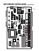
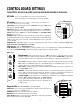
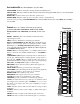
CONTROL BOARD SETTINGS
THESE SETTINGS SHOULD BE ADJUSTED ONLY BY AN EXPERIENCED INSTALLER OR TECHNICIAN!
RST/LEARN:
1) Use to set transmitter code in control board memory.
2) Press this button to clear the diagnostic and error LEDs.
DIP switches (To change these settings, you must turn power OFF; move
the switch; then turn power back ON.)
SWNG/SLD (swing or slide gate operation): SWNG = swing gate SLD = slide
gate [factory default is SLD].
MAST/SLV (master or slave unit): This DIP switch must be set to MAST for
single gate applications. For dual gate applications set one control board to
MAST and the other to SLD [factory default is MAST]. See Installing a Dual
System on pages 21-22.
GATE R/L (gate opens right or left): The direction a gate opens is determined
by standing inside the property and facing toward the gate. Set the DIP switch
to R for a gate that opens to the right. Set the DIP switch to L for a gate that
opens to the left.
SEQUENCE 1: This DIP switch is used for sequencing slide gates [factory default is OFF]. For single gate
applications this switch MUST be set to OFF.
SEQUENCE 2: Same as SEQUENCE 1 above.
TMR. OFF/ON (auto-close timer OFF or ON; close timer is set to 1 second at the factory): When this DIP switch is
set to ON, the CLOSE TIMER potentiometer must be adjusted [factory default is OFF].
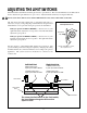
Potentiometers (All potentiometers are set to MIN at the factory. The size and type of gate
installation must be accommodated by adjusting the potentiometers. HOWEVER–potentiometer
settings should not be used to compensate for worn, damaged, or improper gate hardware.)
CLS. SENS. (closing sensitivity): Adjusts obstruction sensitivity of the gate in closing mode. The
MIN setting is for minimum gate force. The MAX setting is for maximum gate force (i.e., the
operator will require greater resistance before obstructing).
OPN. SENS. (opening sensitivity): Adjusts obstruction sensitivity of the gate in opening mode
(see CLS. SENS. above).
INERTIA: This potentiometer fine tunes the operator obstruction settings in the open and close
modes. This potentiometer can be adjusted to allow the operator to push against an obstruction
for a maximum of 2 seconds before “obstructing” (i.e., stopping and reversing).
CLOSE TIMER: Controls the auto-close feature (factory default is 1 s): Is disabled and enabled
with the TMR. OFF/ON DIP switch (see DIP switches
above). The potentiometer adjusts the amount of time that
the gate will remain open before it closes. The limits are 1
to 120 seconds.
Diagnostic LEDs (Press RST / LEARN to clear these LEDs)
PWR OK: Power (115 Vac) is being delivered to the unit. This light will not be
on when operator is in “LEARN” mode.
TIMER ON: The auto-close timer has been enabled.
OBSTRUCT: An obstruction has been encountered.
MAX TIME: Indicates operator ran longer than 60 seconds without reaching a
limit switch and the motor has shut OFF.
123456
ON
SWNG/SLD
MAST/SLV
GATE R/L
SEQUENC 1
SEQUENCE 2
TMR. OFF/ON
EDGE 6
EDGE 5
ST / LEARN
DIP switches
MIN MAX
CLS. SENS.
MIN MAX
OPN. SENS.
MIN MAX
INERTIA
1 120
60
CLOSE TIMER
Potentiometers
PWR OK
TIMER ON
OBSTRUCT
MAX TIME
SENSOR ERR.
LIM SW ERR.
OPEN MTR.
INTERN.ERR.
Diagnostic LEDs