
User Guide
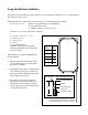

Wiring the Loop Detector to GTO Systems
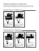
Wiring the detector as a Shadow Loop
Always make sure the power switch to the operator is turned off before connecting accessory device
wiring to the terminal blocks. Unplugging the transformer does not turn power to the operator OFF.
PRO-SW3000 & PRO-SW4000
Mighty Mule 500 & 502
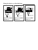
Wiring the detector as a Safety Loop
PRO-SW3000 & PRO-SW4000
Mighty Mule 500 & 502
Wires from relay output
on detector
STALL FORCE
M
I
N
M
A
X
GRN
BLK
RED
RECEIVER
COM COM
CYCLE
CLOSE
SAFETY
EXIT
OPEN
SHADOW
LOOP
CLOSE
EDGE
OPEN
EDGE
J11
J8
J12
Connect one of the relay output wires
from the detector to the COMMON
(COM) terminal and the other to the
SAFETY terminal.
Connect one of the relay output wires
from the detector to the COMMON
(COM) terminal and the other to the
SHADOW LOOP terminal.
Connect one of the relay output wires
from the detector to the COMMON
(COM) terminal and the other to the
SHADOW LOOP terminal.
Wires from relay output
on detector
RECEIVER
COM COM
CYCLE
CLOSE
SAFETY
EXIT/
OPEN
SHADOW
LOOP
CLOSE
EDGE
OPEN
EDGE
BLKGRN RED
STALL FORCE
M
I
N
M
A
X
Wires from relay output
on detector
STALL FORCE
M
I
N
M
A
X
GRN
BLK
RED
RECEIVER
COM COM
CYCLE
CLOSE
SAFETY
EXIT
OPEN
SHADOW
LOOP
CLOSE
EDGE
OPEN
EDGE
J11
J8
J12
Wires from relay output
on detector
RECEIVER
COM COM
CYCLE
CLOSE
SAFETY
EXIT/
OPEN
SHADOW
LOOP
CLOSE
EDGE
OPEN
EDGE
BLKGRN RED
STALL FORCE
M
I
N
M
A
X
Connect one of the relay output wires
from the detector to the COMMON
(COM) terminal and the other to the
SAFETY terminal.
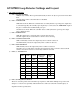
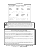
PRO-SL1000 & PRO-SL2000
Connect one of the relay output wires
from the detector to the GREEN
(GRN) terminal and the other to the
ORANGE (ORG) terminal.
ON
ALARM ACCESSORY RCVR
SEQ1
SEQ2
LEARN
BLU
ORG
WHT
GRN
R B G
Wires from relay
output on detector