Digital Loop Detector GTO, Inc. • 3121 Hartsfield Road • Tallahassee, Florida 32303 1-800-543-GATE (4283) • www.gtoinc.
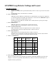
GTO/PRO Loop Detector Settings and Layout 1) DIP SWITCH SETTING: a) DIP 1: PRESENSE TIMER OFF (Factory default): The loop will automatically re-tune if an object is present for more than 1 hour. ON: Automatic retune as described above is disabled. b) DIP 2: SAFE/SECURE OFF: Fail-safe mode. When the controller detects a fault (shorted or open loop) the output relay is activated.
2) LED INDICATORS: a) RED LED: The red LED blinks when power is present. b) GREEN LED: The green LED blinks when detection occurs. NOTE: Both LEDs blink when fault is detected at the loop. 3) TERMINAL BLOCK (PLUGGABLE): a) OUTPUT RELAY: Relay is ‘dry-contact’ output. i) TB1-1: Normally open side of output relay. ii) TB1-2: Common side of output relay. iii) TB1-3: Normally closed side of output relay. b) POWER SUPPLY INPUT: i) TB1-4: 8-26 Vac/Vdc positive input. ii) TB1-5: 8-26 Vac/Vdc negative input.
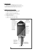
Loop Installation Guidelines The typical sensing height is 2/3 of the shortest leg of a loop (in feet). Therefore a 4’ x 8’ loop typically has a detection range of 2.6’.
4. When the outline of the loop and the lead-in has been marked the pavement can be cut. The saw cut should be approximately 2.0 inches deep and 0.25 inches wide. All 90 degree corners should be chamfered so that the course of the loop wire does not change direction sharply but rather at shallow angles of 45 degrees or less. The saw slot should be cleaned out and allowed to dry. 5. Loop wire is typically 14, 16, 18, or 20 AWG with cross-linked polyethylene insulation, rated for direct burial.
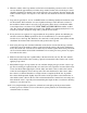
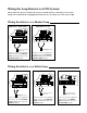
Wiring the Loop Detector to GTO Systems Always make sure the power switch to the operator is turned off before connecting accessory device wiring to the terminal blocks. Unplugging the transformer does not turn power to the operator OFF.
Wiring the detector as a Free Exit Loop PRO-SW3000 & PRO-SW4000 PRO-SL1000 & PRO-SL2000 Mighty Mule 500 & 502 STALL FORCE WHT BLU ORG GRN R B G GRN BLK RED Wires from relay output on detector Connect one of the relay output wires from the detector to the COMMON (COM) terminal and the other to the EXIT OPEN terminal.
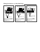
Conversion Chart Converting Metric Units to English Equivalents When You Know Multiply By To Find Symbol centimeters meters kilograms 0.3937 3.2808 2.2046 inches feet pounds in. (or “) ft. (or ‘) lb. (or #) Converting English Units to Metric Equivalents When You Know Multiply By To Find Symbol inches feet pounds 2.5400 0.3048 0.4535 centimeters meters kilograms cm m kg Converting Temperature deg. Celsius deg. Fahrenheit (ºC x 1.8) + 32 deg. Fahrenheit (ºF-32) ÷ 1.8 deg.