IMPORTANT: 16 gauge, multi-stranded, direct burial, low voltage wire (RB509) is required to connect the lights to the digital control board (see diagram on page 1). Small sections of the same wire will also be required for connecting light kit control board to gate operator control board and power source. Please read manual to determine how much wire you will need.
Thank you... for purchasing the Digital Controlled Gate Opener Light Kit. GTO, Inc., has been designing and manufacturing reliable, high quality products since 1987. Our corporate headquarters and state of the art manufacturing facility is located in Tallahassee, Florida. One of our highest priorities is to provide outstanding technical service to our customers.
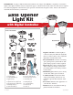
BEFORE YOU START... HOW THE DIGITAL LIGHT KIT WORKS: The Digital Light Kit is designed to work in conjunction with GTO automatic gate openers to illuminate the entry way while the gate is being opened and closed during night time hours. The low voltage lights are controlled by a digital control board that is connected to the gate opener’s controller. The lights are activated when the gate begins to open and can be adjusted to remain on for up to 120 seconds.
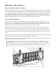
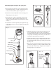
INSTALLING THE LIGHTS Installing lights on the face of the gate post: 1. Insert small screws into holes on the underside of lens hood as shown in Figure 1. Only screw them part way so they can twist lock into place on top of lens. 2. Install wires into the light bulb socket by simply pressing a brass connector into each side of the socket until it snaps into place. See Figure 2. Figure 1 3. Line up the slots on the socket with the notches in the lens. Insert the scoket into the lens.
Installing lights on top of the gate post: 1. Insert small screws into holes on the underside of lens hood as shown in Figure 7. Only screw them part way so they can twist lock into place on top of lens. 2. Install wires into the light bulb socket by simply pressing a brass connector into each side of the socket until it snaps into place. See Figure8. Figure 7 3. Line up the slots on the socket with the notches in the lens. Insert the scoket into the lens.
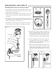
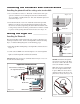
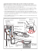
Installing the Photocell and Control Board Installing the photocell and low voltage wire strain relief: 1. Use a screwdriver to remove a “knockout” in the bottom of the gate operator control box or a weatherproof junction box. If knockouts are not available, carefully drill a 5/8” hole, then install the photocell as shown in Figure 13. Figure 13 2. In another knockout or 5/8” hole, install the strain relief provided. Run the low voltage wire from the lights through the strain relief into the box.
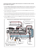
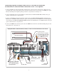
Connecting Light Kit to Mighty Mule FM500/502, GTO/PRO SW2500, SW3000, and SW4000 Gate Openers: 1. Connect the RED wire from the Light Kit control board and a short section of 16 gauge low voltage wire (not provided) to the RLY-COM (Relay Common) terminal on the gate opener control board. Connect the other end of the short section of wire to the RED gate opener battery lead using the wire splicing locks provided. See diagram below and Figure 16. 2.
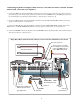
Connecting Light Kit to Mighty Mule FM700, GTO/PRO SW1000, SW2000, SL1000 and SL2000 SINGLE Gate Openers: 1. Connect the RED wire from the Light Kit control board to a short section of 16 gauge low voltage wire (not provided) using a wire nut provided. Connect the other end of the JUMPER wire to the RED gate opener battery lead using the wire splicing locks provided. See diagram below and Figure 16. 2.
Connecting Light Kit to Mighty Mule FM702, GTO/PRO SW1000/1200, SW2000/2200, SL1000/1200 and SL2000/2200 DUAL Gate Openers: 1. Connect the RED wire from the Light Kit control board to a short section of 16 gauge low voltage wire (not provided) using a wire nut provided. Connect the other end of the short section of wire to the RED gate opener battery lead using the wire splicing locks provided. See diagram below and Figure 16. 2.
Connecting Light Kit to Mighty Mule 350 and GTO/PRO-SW1500 Openers NOTE: When the Light Kit is used with the Mighty Mule 350 or the GTO/PRO-SW1500, a weatherproof junction box (not included) must be used to house the Light Kit control board and Photocell. Weatherproof junction boxes can be found at your local hardware or electrical supply stores. 1.
Programming the Light Kit Adjusting the Time-On Delay: The Light’s Time-On can be set to leave the lights on from 0-120 second from the time the gate stops. 1. To set the Time-On from 0-60 seconds disconnect the jumper (X2) on the control board. Using a small screwdriver, turn the potentiometer to the time you desire between 0-60 seconds. See Figure 14. Potentiometer set between 0-60 seconds Jumper X2 is disconnected 2. To set the Time-On from 0-120 seconds connect the jumper (X2) on the control board.
Conversion Chart Converting Metric Units to English Equivalents When You Know Multiply By To Find Symbol centimeters meters kilograms in. (or “) ft. (or ‘) lb. (or #) 0.3937 3.2808 2.2046 inches feet pounds Converting English Units to Metric Equivalents When You Know Multiply By To Find Symbol inches feet pounds cm m kg 2.5400 0.3048 0.4535 centimeters meters kilograms Converting Temperature deg. Celsius (ºC x 1.8) + 32 deg. Fahrenheit ºF deg. Fahrenheit (ºF-32) ÷ 1.8 deg.