
User Guide

5
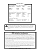
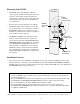
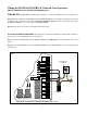
Connecting the Range Adjustment Control Board:
Step 9: Connect the YELLOW wire from the WAND CABLE to the YELLOW wire from the Range Adjust-
ment control board using one of the WIRE NUTS provided.
Step 10: Connect the BLACK wire from the Range Adjustment control board to the BLACK BATTERY
CONNECTOR wire (provided), along with the SHIELD wire from the WAND CABLE (see Step 13 below).
Step 11: Secure the RANGE ADJUSTMENT CONTROL BOARD inside the gate operator control box. The con-
trol box has a slot on the side and bottom for extra control boards, or you can use the optional mounting hole.
IMPORTANT: DO NOT let exposed wiring or components on the control board make contact with other exposed
wiring or components.
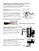
Potentiometer (POT)
Range Adjustment
Control Board
Wire NutWire Nut
Optional Mounting Hole
YELLOW wire
from WAND Cable
YELLOW
BLACK
BLACK BATTERY
CONNECTOR wire provided
MIN MAX
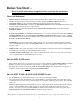
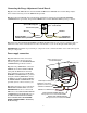
Power supply connection:
Step 12: With Power Off, connect the
RED and BLACK control board wires
from the operator to the DOUBLE SPADE
CONNECTORS (provided) as shown.
Step 13: Using a WIRE NUT, connect the
SHIELD wire from the WAND CABLE
(along with the BLACK wire from the
Range Adjustment board) to the BLACK
BATTERY CONNECTION wire provided
Using the remaining WIRE NUT connect
the RED wire from the WAND CABLE to
the RED BATTERY CONNECTION wire
provided. (Do not connect to battery yet).
Step 14: Connect these wires to the DOU-
BLE SPADE CONNECTORS as shown.
IMPORTANT: Be sure to connect both
RED wires to the same DOUBLE SPADE
CONNECTOR and both BLACK wires to
the other DOUBLE SPADE CONNEC-
TOR. You will connect the DOUBLE
SPADE CONNECTORS to the battery
in the next step.
RED Wire from WAND Cable
SHIELD from WAND Cable
BLACK W
ire from Range
Adjustment control board
BLACK Opener Battery Wire
BLACK BATTERY CONNECTION Wire
with Spade Connector included with W
AND
RED BATTERY CONNECTION Wire
with Spade Connector included with WAND
Double Spade Connectors
included with WAND
RED Operator Battery Wire