
User Guide

4
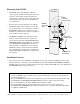
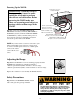
WAND Wires
ON
ALARM ACCESSORY RCVR
SEQ1
2
LEARN
BLU
ORG
WHT
GRN
R B G
BLACK
BLUE
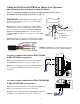
IMPORTANT: TURN OFF the power and disconnect
the battery wires before you begin to connect the WAND
wires to any gate operator.
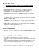
Step 5: Run the cable from the WAND through the WIRE
CLAMP into the control box. Pull about 8 - 10 inches of wire
into the control box to reach the ACCESSORY TERMINAL
BLOCK and BATTERY WIRES in the control board. Now
tighten the WIRE CLAMP nut to secure the wires in the WIRE
CLAMP.
Step 6: Strip about 3/8 of an inch of insulation from the YEL-
LOW, BLACK, RED and BLUE wires in the WAND CABLE.
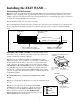
Wiring the WAND to GTO/PRO Low Voltage Gate Operators:
PRO-SW1000/2000, PRO-SW3000/4000 and PRO-SL1000/2000
If you are installing the WAND on an AC Powered Operator skip forward to Page 7.
For installation on other brands of operators, see page 10.
NOTE: The SHIELD is the braided metal wire wrapped
around the insulated wires inside the WAND CABLE.
PVC Conduit
WIRE CLAMP in Knockout
Bottom of Control Box
CABLE from
the Opening Sensor
WIRE from
the Operator
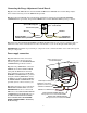
Accessory terminal connection for PRO-SW3000
& PRO-SW4000 gate operators:
Step 7: Connect the BLUE wire from the WAND CABLE to
the EXIT/OPEN terminal on the operator control board.
Step 8: Connect the BLACK wire from the WAND CABLE
to one of the the COMMON terminals on the operator con-
trol board.
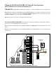
Accessory terminal connection for PRO-SW1000/2000
& PRO-SL1000/2000 gate operators.
Step 7a: Connect the BLUE wire from the SENSOR CABLE to the
BLU Accessory Terminal on the opener control board.
Step 8b: Connect the BLACK wire from the SENSOR CABLE to
the GRN Accessory Terminal on the opener control board.
STALL FORCE
M
I
N
M
A
X
GRN
BLK
RED
RECEIVER
COM
COM
CYCLE
CLOSE
SAFETY
EXIT
OPEN
SHADOW
LOOP
CLOSE
EDGE
OPEN
EDGE
J11
J8
J12
WAND
Wires
BLACK
BLUE