
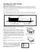
User Guide


10
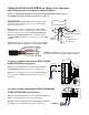
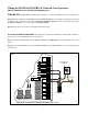
Typical Gate Wiring Connection:
• Reference Wires:
o RED => Input Voltage (+)
o SHIELD => Ground/Common (–)
o BLACK => Relay’s Common
o BLUE => Relay’s Normally Open
o YELLOW => Remote WAND [Range adjustment potentiometer (POT)]
• Terminology Definitions:
o ‘FREE EXIT/ENTRY’: defined as input terminals (2) that upon activation (momentarily connected together) will
cause the gate to run in the open direction only. Note: In most gate operators, one of the two terminals is the ‘COM-
MON/GND’.
• Power supply connection:
o DC power supply: (11-36 Vdc)
ß Connect the positive (+) wire of the power supply to the RED wire.
ß Connect the negative (-) wire of the power supply to the SHIELD wire.
o AC power supply: (8-26 Vac)
ß Connect the power supply to the RED & SHIELD wires. There is no polarity for AC power supply.
• Relay output connection:
o Connect the BLUE from the WAND to the ‘FREE EXIT/ENTRY’ of the gate operator.
o Connect the BLACK from the WAND to the ‘COMMON/GND’ of the gate operator.
• Range (POT) board connection:
o Connect the YELLOW from the WAND to the YELLOW from the Range Adjustment Board.
o Connect the BLACK from the Range Adjustment Board to a negative input voltage.
o Turn the POT clockwise to increase range.
o Turn the POT counter-clockwise to decrease range.
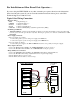
For Installation on Other Brand Gate Operators ...
If you are using the EXIT WAND on any other automatic gate operator brand, use the information
below for wiring the system. If you do not understand the instructions below, please call GTO’s
Technical Support at 1-800-543-1236.
Input
Voltage (+)
Input
Voltage (–)
Relay Output
Common
Relay Output
Normally Open
Range
Adjustment
Range
Adjustment
Board
Input Voltage
11 - 36 Vdc or
8 - 26 Vac
–
+
Free Exit/Entry
Connections
WAND
RED
SHIELD
BLACK
BLACK
BLUE
YELLOW
YELLOW
Generic Wiring Diagram