
User Guide


9
MIN MAX
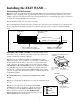
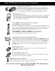
Safety Precautions:
Step 16a: Place the WARNING SIGNS on both
sides of the gate.
!
WARNING
GA
TE OPENING
SENSOR IN USE
The Automatic Gate Opener is activated when a
vehicle comes within range of the sensor buried
along side the driveway and could possibly be
activated by a child on a bicycle, tricycle or other
metal play equipment.
8.5"
4.38"
REWWARN01
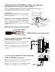
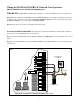
Power supply connection: (See Illustration A on page 7 for BASIC unit control boards and Illustration B
on page 8 for ADVANCED unit control boards.)
Step 12a: Connect the RED wire from the WAND CABLE to the POSITIVE (+) terminal of the 24 VDC Acces-
sory Power Terminal Block on the control board.
Step 13a: Connect the SHIELD from the WAND CABLE to the NEGATIVE (–) terminal of the 24 VDC Acces-
sory Power Terminal Block on the control board.
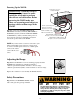
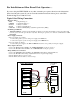
Adjusting the Range:
Step 15a: Test the WAND to see if it is working properly and if the
RANGE needs adjusting for optimum performance.
• Turn the potentiometer (POT) clockwise to increase range.
• Turn the potentiometer (POT) counter-clockwise to decrease range.
Replace the control box cover and bury the WAND and wire.
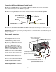
Powering Up the WAND:
IMPORTANT: When the WAND is first powered up it
must be undisturbed for 60 seconds to perform the self
test and calibrations. Before powering the WAND make
sure there are no moving metal objects or moving ve-
hicles within range of the WAND.
Step 14a: Turn power to the operator on, wait 60 seconds before activating the operator and testing the WAND.