
User Guide


8
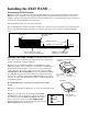
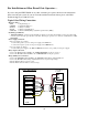
Illustration B
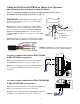
Connecting the Range Adjustment Control Board:
Step 9a: Connect the YELLOW wire from the WAND CABLE to the YELLOW wire from the Range Adjust-
ment control board using the WIRE NUT provided.
Step 10a: Connect the BLACK wire from the Range Adjustment control board and the SHIELD wire from
the WAND CABLE to the NEGATIVE (–) side of the 24 VDC Accessory Terminal on the control board.
Step 11a: Secure the RANGE ADJUSTMENT CONTROL BOARD inside the gate operator control box.
IMPORTANT: DO NOT let exposed wiring or components on the control board make contact with other exposed
wiring or components.
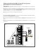
Potentiometer (POT)
Range Adjustment
Control Board
Wire Nut
Optional Mounting Hole
YELLOW wire
from WAND
YELLOW
BLACK
To
NEGATIVE (–) Terminal
of the 24VDC Accessory
Terminal on the Control Board
MIN MAX
YELLOW
MIN MAX
INERTIA
EDGE 6
EDGE
5
EDGE
4
EDGE
3
EDGE
2
EDGE
1
COM
COM
–
+
DUAL GATE
INTERFAC
E
RX
TX
GRN
RED
BLK
GTO
RCVR.
LOCK 1
LOCK 2
ALARM
AUX 2
ACCES.
PWR.
24VDC
–
+
–
+
MIN MAX
CLS. SENS.
MIN MAX
OPN. SENS.
CYCLE
FREE
EXIT
CLOSE
OPEN
FIRE
DEPT.
SHAD
.
LOOP
SAFETY
LOOP
ENTRY
LOOP
1 120
TIMER
COM
COM
COM
COM
RED
SHIELD
BLACK
BLACK
BLUE
YELLOW
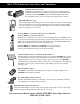
Wire Nut
Cable from Sensor
GTO/PRO AC SL-5100/6100 and SW-5100/6100 ADVANCED Control Board
Range Adjustment
Control Board
MIN MAX