
User Guide

7
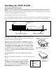
Wiring the WAND to GTO/PRO AC Powered Gate Operators:
PRO-SL5000/6000, Series and PRO-SW5000/6000 Series
IMPORTANT: TURN OFF the power before you begin to connect the WAND wires to the control board.
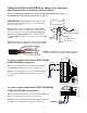
Step 5a: Run the cable from the WAND through the WIRE CLAMP into the control box. Pull about 8 -10 inches
of cable into the control box to reach the ACCESSORY TERMINAL BLOCKs on the control board. Now tighten
the WIRE CLAMP nut to secure the cable in the WIRE CLAMP.
Step 6a: Strip about 3/8 of an inch of insulation from all the wires.
Illustration A
–
+
G
R
B
GTO
RCVR.
1/2 amp
slow blow fuse
CLOSE
OPEN
FIRE DEPT
.
SHAD. LOOP
SAFE LOOP
ENTRY LOOP
FREE EXIT
CYCLE
COMMON
COMMON
COMMON
COMMON
LOCK 1
LOCK 2
AUX 2
AUX 1
ACCES. PWR
Class
2
24VDC
REV
FWD
GTO Inc., Tallahassee, FL
copyright 1999
TB11
TB10
TB9
TB8
TB7
TB6
TB5
TB4
TB3
RED
SHIELD
BLACK
BLACK
BLUE
YELLOW
YELLOW
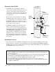
Range Adjustment
Control Board
Wire Nut
MIN MAX
Cable from Sensor
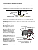
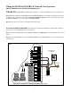
GTO/PRO AC SL-5000/6000 and SW-5000/6000 BASIC Control Board
Accessory terminal connection: (See Illustration A below for BASIC unit control boards and Illustra-
tion B on page 8 for ADVANCED unit control boards.)
Step 7a: Connect the BLUE wire from the WAND CABLE to the FREE EXIT Accessory Terminal on the control
board.
Step 8a: Connect the BLACK wire from the WAND CABLE to the COM (Common) Accessory Terminal on the
control board.