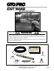
INSTALLATION MANUAL WARNING When an EXIT WAND is in use, the automatic gate operator could be activated by a child on a bicycle, tricycle or other metal play equipment. This product is not recommended for applications exposed to children. If you are installing this product on an AC powered gate operator, we recommend you consult a certified electrician.
Thank You ... for purchasing the GTO/PRO® EXIT WAND. This product requires no maintenance and will give you years of enjoyment by providing hands free operation of your gate. GTO, Inc. has been designing and manufacturing reliable, high quality products since 1987. Our corporate headquarters and state of the art manufacturing facility is located in Tallahassee, Florida. One of our highest priorities is to provide outstanding technical service to our customers.
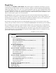
Conversion Chart Converting Metric Units to English Equivalents When You Know Multiply By To Find Symbol centimeters meters kilograms 0.3937 3.2808 2.2046 inches feet pounds in. (or “) ft. (or ‘) lb. (or #) Converting English Units to Metric Equivalents When You Know Multiply By To Find Symbol inches feet pounds 2.5400 0.3048 0.4535 centimeters meters kilograms cm m kg Converting Temperature deg. Celsius deg. Fahrenheit (ºC x 1.8) + 32 deg. Fahrenheit (ºF-32) ÷ 1.8 deg.
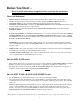
Before You Start ... Please read the instructions completely before you begin the installation. Terms and Definitions: • • • • • • METAL OBJECT: anything that is made of iron based metal, from a child’s toy to a car or truck. WAND: the magnetic device inside the waterproof tube that detects METAL OBJECTS in motion. MAGNETIC FIELD: an area around the WAND where metal in motion can be detected.
Placement of the WAND: • • • Driveway The WAND comes with 50, 100 or 150 feet of cable. A typical installation will require about 5 feet of wire to come from the ground up and into the control box for connection to the power supply and control board. Check your specific installation for exact dimensions. WAND: 2 feet from driveway (max) RANGE: 12 ft.
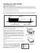
Installing the EXIT WAND ... Determining WAND Location: Step 1: Determine the optimum location for the EXIT WAND using the information found in “Placement of the WAND” on page 2. Then dig a hole approximately 12 inches deep and 24 inches long within two (2) feet and parallel to the edge of the driveway. Next, dig a trench from this hole to a spot under the gate operator control box to run the wire from the WAND to the control box. Keep the WAND and the cable uncovered at this time.
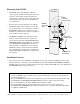
Wiring the WAND to GTO/PRO Low Voltage Gate Operators: PRO-SW1000/2000, PRO-SW3000/4000 and PRO-SL1000/2000 If you are installing the WAND on an AC Powered Operator skip forward to Page 7. For installation on other brands of operators, see page 10. IMPORTANT: TURN OFF the power and disconnect the battery wires before you begin to connect the WAND Bottom of Control Box wires to any gate operator. Step 5: Run the cable from the WAND through the WIRE CLAMP into the control box.
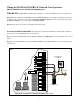
Connecting the Range Adjustment Control Board: Step 9: Connect the YELLOW wire from the WAND CABLE to the YELLOW wire from the Range Adjustment control board using one of the WIRE NUTS provided. Step 10: Connect the BLACK wire from the Range Adjustment control board to the BLACK BATTERY CONNECTOR wire (provided), along with the SHIELD wire from the WAND CABLE (see Step 13 below).
Powering Up the WAND: Double Spade Connectors included with WAND IMPORTANT: When the WAND is first powered up it must be undisturbed for 60 seconds to perform the self test and calibrations. Before powering the WAND make sure there are no moving metal objects or moving vehicles within range of the WAND.
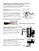
Wiring the WAND to GTO/PRO AC Powered Gate Operators: PRO-SL5000/6000, Series and PRO-SW5000/6000 Series IMPORTANT: TURN OFF the power before you begin to connect the WAND wires to the control board. Step 5a: Run the cable from the WAND through the WIRE CLAMP into the control box. Pull about 8 -10 inches of cable into the control box to reach the ACCESSORY TERMINAL BLOCKs on the control board. Now tighten the WIRE CLAMP nut to secure the cable in the WIRE CLAMP.
Connecting the Range Adjustment Control Board: Step 9a: Connect the YELLOW wire from the WAND CABLE to the YELLOW wire from the Range Adjustment control board using the WIRE NUT provided. Step 10a: Connect the BLACK wire from the Range Adjustment control board and the SHIELD wire from the WAND CABLE to the NEGATIVE (–) side of the 24 VDC Accessory Terminal on the control board.
Power supply connection: (See Illustration A on page 7 for BASIC unit control boards and Illustration B on page 8 for ADVANCED unit control boards.) Step 12a: Connect the RED wire from the WAND CABLE to the POSITIVE (+) terminal of the 24 VDC Accessory Power Terminal Block on the control board. Step 13a: Connect the SHIELD from the WAND CABLE to the NEGATIVE (–) terminal of the 24 VDC Accessory Power Terminal Block on the control board.
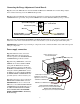
For Installation on Other Brand Gate Operators ... If you are using the EXIT WAND on any other automatic gate operator brand, use the information below for wiring the system. If you do not understand the instructions below, please call GTO’s Technical Support at 1-800-543-1236.
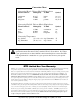
TECHNICAL SPECIFICATIONS: • • • Power supply: 8-26 Vac/dc. Current consumption: 1.5 mA typical. Relay rating: Latching relay Nominal switching capacity (resistive load) Max. switching power (resistive load) Max. switching voltage Max. switching current • • • • • 1 Amp 30 Vdc, 0.5 Amp 125 Vac 30 Watt, 62.5 V A 110 Vdc, 125 Vac 1 Amp Relay Trip Time: 2 seconds Operating Temperature: -25°F (-14°C) to 125°F (69°C) Dimensions: 1-3/4” (44.5 mm) diameter x 16.5” (42 cm) long.
Other GTO Products for Your Safety and Convenience: Automatic Gate Lock (FM144) A MUST for securing the gate against forced entry or exit. Solenoid driven, plated steel bolt lock with a zinc plated steel housing. The horizontal electronic lock is used with the GTO/PRO system for maximum stability and security. Recommended for gates over 8 feet long or where high winds are common.