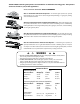
OWNER’S MANUAL GP-SW050 Residential Duty Swing Gate Operator TWO 12VDC, U1, 230A BATTERIES ARE REQUIRED BUT NOT INCLUDED. DO NOT Install This Operator Without Safety Edges and Photo Beams! APPROPRIATE ENTRY/EXIT DEVICES WILL BE REQUIRED - SEE YOUR DEALER. This product meets and exceeds the requirements of UL 325 gate operator safety standards. LISTED For more information on GTO’s full line of automatic gate openers and access controls visit our website at www.gtoaccess.
The GP-SW050 automatic gate operators are intended for use with vehicular swing gates. The operators can be used in Class I, II, III, and IV applications. vehicular gate operator class categories Class I: Residential Vehicular Gate Operator – A vehicular gate operator (or system) intended for use in a home of one-to-four single family dwelling, or a garage or parking area associated therewith.
Table of Contents Gate Operator Class Categories.......................................................................................Inside Cover Metric Conversion Chart...........................................................................................................................Inside Cover Safety Instructions for the GP-SW050 Swing Gate Operators.....................................................1 Important Safety Instructions for the System Designer.......................................
Important Safety Instructions Safety Instructions for the GP-SW050 SWING Gate OperatorS Because automatic gate operators produce high levels of force, all system designers, installers, and consumers have an obligation to know the potential hazards associated with improperly designed, installed, or maintained gate operator systems. Keep in mind that the gate operator is just one component of the total gate operating system.
Important Safety Instructions Important Safety Instructions For the Installer WARNING–To reduce the risk of injury or death: I. Before Installation 1. READ AND FOLLOW ALL INSTRUCTIONS. 2. Verify this operator is proper for the type and size of gate, and its frequency of use. 3. Make sure that the gate has been properly installed and swing freely in both directions. Repair or replace all worn or damaged gate hardware prior to installation.
Important Safety Instructions Important Safety Instructions Specific to Secondary Means of Protection Against Entrapment As specified by Underwriters Laboratories Inc. UL 325 (30A.1.1), automatic gate operators shall have provisions for, or be supplied with, at least one independent primary and one independent secondary means to protect against entrapment. GTO gate operators utilize Type A, an inherent entrapment sensing system, as the primary type of entrapment protection.
Important Safety Instructions Important Safety Instructions for the Consumer/End User WARNING: To reduce the risk of injury or death: 1. READ AND FOLLOW ALL INSTRUCTIONS. 2. Distribute and discuss copies of the IMPORTANT SAFETY INSTRUCTIONS manual with all persons authorized to use your gate. SAVE THESE INSTRUCTIONS. 3. Always keep people and objects away from the gate and its area of travel. NO ONE SHOULD CROSS THE PATH OF THE MOVING GATE. 4. Your automatic gate is not for pedestrian use.
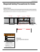
Important Safety Instructions Required Safety Precautions for Gates Entrapment Protection GTO’s internal obstruction settings, even when properly adjusted, may not be sensitive enough to prevent bodily injury. For this reason, safety devices such as safety edges and photo beams MUST be installed. Furthermore, a walk-through gate must be installed if pedestrian traffic is expected near the gate. We recommend the GTO Bulldog Pedestrian Gate Lock (available as an accessory) for controlled access.
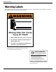
Important Safety Instructions Warning Labels These warning signs and labels should be found at the locations specified below. If any of them are missing, immediately contact your installer for replacements. ! WARNING Moving Gate Can Cause Injury Or Death 1. KEEP CLEAR! Gate may move at any time. 2. Do not allow children to operate gate or play in gate area. 3. This gate is for vehicles only. Pedestrians must use a separate entrance.
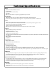
Technical Specifications Motor • Brushless DC motor 24VDC 300 watts • ½ Horsepower • Maximum motor current 20Amp • 2500 RPM • Open and close time for 90° opening is approximately 15 seconds Gear Reducer • Aluminum Cased 1200:1, size 40/63, compound, worm reducer with ball bearings.
Parts Identification Fully Assembled Operator 13 in (33 cm) Operator Chassis 12½ in (31.8 cm) 17 in (42 cm) 27 in (69 cm) 23¾ in (60.3 cm) 19¾ in (50.2 cm) 24 in (61 cm) 33 in (84 cm) TO BASE 18 in (46 cm) 6 in (15.2 cm) 15 in (38 cm) NOTE: GTO receiver (RB709U), batteries (12vdc, U1, 230A minimum) not included. Must order separately. 14½ in (36.8 cm) 12½ in (31.8 cm) 3 in (7.
Installing the Gate Operator This unit must only be installed by an experienced technician. Preparation of the Gate Before installing the GTO swing gate operator, make sure: • the gate is properly installed. • the gate is plumb, level, and moves freely. • the gate does not bind or drag on the ground. Overview of a Single Gate Operator Installation The diagram below is an example of a single swing gate installation with required safety features. The operator must be installed on the inside of the gate.
Using the Mounting Template The mounting template (see insert) is designed to simplify mounting the operator. It provides the installer with the proper locations for running power and accessory wiring conduits. The template is also marked with the correct distance between the operator mounting holes and shows the installer how to position the operator for the correct clearance between the housing and the gate. NOTE: The operator must be securely mounted on a level concrete pad.
Mounting Template (NOT TO SCALE) Drill 3/8” x 3” deep 6 places. Use 3/8” wedge type anchors. 3” Output Shaft 4 5/8” 6 3/8” 2½” Gate open position 11” 10” Gate closed position 18½“ From Hinge Centerline Concrete pad 16” x 16”. Consult local building codes for depth below ground. Absolute minimum depth 30” below ground level.
Removing the Operator Housing Before you can gain access to the operator frame and its mounting holes, the housing will have to be removed from the operator. 1. Remove the (2) 3/8” allen bolts and (2) m8 washers from the operator housing (this hardware is located on each side of the housing). 2. Lift the housing off the operator and set it aside. Allen Bolts with 5mm key Washers Mounting the Operator 1.
Connecting Power to the Operator 1. Turn the breaker power switch off before connecting AC power. Have a licensed electrician run 115 Vac wiring into the Field Wiring Connection Compartment. The 115 Vac line will power the gate operator system. The circuit must be protected with a 15 A main disconnect breaker (not provided). NOTE: Power and wiring connections MUST be performed by a licensed electrician in accordance with NEC (National Electric Code) and local codes. NEVER run low voltage (e.g.
Gate Arm Connection Overview Right Mounted Arm Center point of gate hinge to center of gate bracket pin (approximately) 50” Center point of gate hinge Column Closed Gate Range of Arm Movement 160°-175° 5°-10° Housing Pivot point of operator Opened Gate e CAUTION: DO NOT STAND IN THIS AREA IMPORTANT: Be sure the operator housing will not be hit by a fully open gate and that the gate column will not interfere when housing is installed.
Connecting the Gate Arm to the Gate Key Bolts and Washers Output Shaft Reducer Arm Fig. 1 Fig. 2 1. Install the key into the output shaft. (Fig. 1) 2. Fit the end of the reducer arm onto the output shaft as shown and tighten the bolts. (Fig. 2) 3. Turn the power on. 4. Set DIP switch 1 to designate the operator arm as left or right (Fig. 3) (right is shown here). 5. Manually move gate to the closed position. (Fig. 4) ON ON ON >>> SIMUL SLAVE SECURE MODE 1 MODE 2 OPEN DIR.
EXIT SHADOW SAFETY GTO LOOP DETECTORS ALARM 3 COM LINK COM DUAL CABLE DUAL LINK ACC. POWER 5 BLDC SPEED CONTROL LOCK 13 RUNNING 12 CLOSED 11 20 LOCK COM LOCK N.O. RUN 2 RELAY OUTPUTS RUN 1 DIAG. PORT OPTIONS CLOSED 2 10 CYCLE CYCLE SAFETY SAFETY 9 OPEN EDGE CLOSE EDGE CLOSE EDGE OPEN OPEN CLOSE CLOSE STOP STOP COM COM COM COM W1 CUT TO USE 3 BUTTON STATION MODE 1 MODE 2 OPEN DIR.
Setting the Limits CAUTION: Be extremely careful not to stand in the path of the gate arm while setting limits. OPEN LIMIT SETTING: 1. Turn on operator power. 2. Press and release the OPEN button on the board and be prepared to press the STOP button when the gate reached the desired open position/limit. 3. The JOG buttons can be used to bring the gate to the precise open position. The JOG buttons will slowly run the gate when pressed and stop the gate when released. 4.
Stall Force and Auto-Close Adjustments Stall Force Adjustment: IMPORTANT: For safety reasons, the STALL FORCE potentiometers are set at the “10 o’clock” position at the factory. The obstruction sensitivity is independently adjustable for each direction of travel. Upon sensing an obstruction, the gate will stop and reverse direction for approximately 2 seconds. 1. Turning the potentiometer clockwise (toward the MAX position) increases the amount of force the operator applies to an obstruction.
DIP Switch Settings MODE 1 & MODE 2: • Reserved for future features DIP #1: OPEN DIRECTION • OFF: for gate that opens to the left, closes to the right. • ON: for gate that opens to the right, closes to the left. • • BLDC SPEED CONTROL PRISON MODE These switches are for dual gate applications only. See page 26 for dual gate settings. DIAG. PORT RELAY OUTPUTS OFF: Fail safe mode DUAL LINK When low battery and no AC power conditions are detected the gate will automatically run to the opened position.
E LINK COM LOCK N.C. Input Connections LOCK LOCK COM RELAY OUTPUTS LOCK N.O. NOTE: • All control inputs are dry-contact, normally open, inputs except for #8. DO NOT apply external voltage RUN 1 sources to these inputs. • All inputs are connected with respect to COMMON terminal. RUN 2 • All inputs have a corresponding LED indicator for diagnostic purposes.
CLOSE MA LIMIT AD <<< COM GTO Inc. Tallahassee, FL W1 CUT TO USE 3 BUTTON STATION COM COM COM COM STOP OPEN SAFETY CLOSE 12 13 14 15 16 17 18 19 20 21 22 CYCLE CLOSED 2 CLOSED 1 COM STOP CLOSE OPEN CLOSE EDGE SHADOW OPEN EDGE SAFETY CLOSED 9 10 11 RUN 2 LOCK N.O. LOCK N.C.
Output Connections LOCK COM LOCK N.O. Maximum rating for all relay outputs are 24Vac/dc, 1 Amp. All relay outputs are dry contact (no voltage) switching. All outputs have corresponding LED indicator for diagnostic purposes. The corresponding LED indicator will be lit when its relay is activated. RUN 1 RUN 2 RELAY OUTPUTS Note: • • • LOCK N.C. RUNNING LED10 CLOSED CLOSED 1 1. CLOSED 1 and CLOSED 2: At closed limit relay output.
Accessory Power Supply Connection • • 12Vdc @ 300 mA (.3A) maximum power supply for additional accessories. If you lose power to your accessories, the accessories are protected by a poly-fuse. Disconnect accessories and allow poly-fuse to cool down for 2 minutes before reconnecting. EXIT SHADOW SAFETY ALARM GTO LOOP DETECTORS STATUS +12Vdc COM LINK COM 23 DUAL CABLE DUAL LINK ACC. POWER 12Vdc @ 300 mA Power Supply + ACC. PWR.
Prison Mode Operation (CLASS IV APPLICATIONS) Prison mode operation means that constant pressure at the CLOSE or the OPEN push button station input is required to move the gate in the desired direction. Follow these steps to toggle the PRISON MODE operation on/off: 1. Power down the unit. 2. Press and hold the OPEN and CLOSE push button while powering on the unit. CYCLE 3. The PRISON MODE LED indicator will be on if operating in prison mode. AUTO CLOSE 4.
Reinstalling the Operator Housing Check to make sure the safety edges, photoelectric beams, warning signs, and pedestrian gate (if necessary) are installed (see pages 5-6) before fastening the housing to the operator. 1. 2. Lower the operator housing into position over the operator. 3. Pull sides out slightly so that the housing sits into place properly over the base. Fasten the housing to the operator with (2) Washers and (2) Allen Bolts.
Installing a Dual Gate Operator System IMPORTANT: With a dual gate system certain control board settings and connections are required on the MASTER unit only and some are required on both the MASTER and the SLAVE unit. The list below gives an overview.
Setting Dual Gate Sequence GP-SW050 operators come from the factory with the #2 DIP switches set to OFF. DIP Switches must be changed to accommodate dual gate operation. The information below shows the proper settings for a dual gate application. OPTIONS OFF OFF <<< DELAY MASTER SAFE MODE 1 MODE 2 OPEN DIR. SLV OPN DUAL MODE LOW BATT STALL FORCE ADJUST <<< >>> MAX MIN ON ON >>> SIMUL SLAVE SECURE MODE 1 MODE 2 OPEN DIR.
28 Overview of a Dual Gate Operator Installation Use Rigid Conduit for inbound AC. Operator Run Belden Wire® ONLY in its own conduit, 22 AWG , 1-pair shielded with GROUND. R4222 Safety Edge (NOT INCLUDED) Photo Beams OPTIONAL Closed Position Ground Stop Post and Plate Safety Edge Warning Sign Use PVC Conduit for Receiver Use Rigid Conduit for inbound AC. Operator Operator (NOT INCLUDED) RB709U Receiver Master Operator NOTE: A separate gate or entrance must be installed for pedestrian use.
Maintenance WARNING: ALWAYS TURN OPERATOR OFF AND DISCONNECT AC POWER BEFORE ADJUSTING OR SERVICING IT. Maintenance Schedule: • Test the operator, accessories, and safety devices monthly. • Service the gate operator, accessories, and safety devices regularly. Maintenance Checklist • Test the safety edges to make sure the gate responds. • Check the obstruction settings (both open and close modes) see page 18. • Check for wear on all moving parts, and tighten bolts as necessary.
TroubleShooting Guide WARNING: ALWAYS TURN OPERATOR OFF AND DISCONNECT BATTERIES BEFORE ADJUSTING OR SERVICING IT. GP-SW050 Audible Feedback Symp t o m Diagnosis Ch e c k One beep every 5 seconds when the gate is in motion. There is no AC power present. • • • GFI Circuit Breaker Connections in the Field Wiring Connection Compartment The battery voltage is low.
GP-SW050 Visual Feedback Symp t o m Diagnosis Ch e c k Cycle LED ON brightly Status Light flashes Cycle terminal shorted to Com • • • Safety LED ON brightly Status Light flashes Safety terminal shorted to Com • • • • Shadow LED ON brightly Status Light flashes Shadow terminal shorted to Com Open Edge LED ON brightly Status Light flashes Open Edge terminal shorted to Com 31 • Push button or key on keypad is stuck. Wire between push button, keypad, etc.
Symp t o m Diagnosis Ch e c k Close Edge LED ON brightly Status Light flashes Close Edge terminal shorted to Com • • • • Open LED ON brightly Status Light flashes Open terminal shorted to Com • • • • • Edge sensor is sensing an obstruction. Relay from edge sensor is shorted or latched. Wire between edge sensor and open edge terminal is shorted. Check terminal voltage with respect to Com to ensure you read 12 vdc. Push button is stuck. Exit wand, Loop detector, Photo beam, etc.
Warranty and Repair Service If the GTO gate operator system is not working properly, please follow the steps below: Instructions for the Consumer/End User: 1. Call your dealer or installer for service. Only an experienced technician may service this unit. 2. If your dealer or installer is unable to solve the problem, he will contact the GTO Service Department. Instructions for the Dealer/Installer: 1.
Installation Checklist The installation of this operator conforms to CLASS __________. The installer verifies that (each item must be checked): ____ Required safety edges or photo beams were installed. ____ Customer was informed that this gate is for vehicular use ONLY. Pedestrians MAY NOT use this gate. ____ A separate gate or entrance was installed for pedestrian use. ____ All warning signs and labels were installed as specified in the IMPORTANT SAFETY INSTRUCTIONS.